|
|
|
|
|
|
|

|
|
|
|
|
|
|
|
|
| EMC Test System Controllers |
|
TDK RF Solutions provides innovative solutions for RF, EMI, EMS and Microwave test systems covering a wide range of specifications. Our technical expertise includes: Radiated and Conducted Emissions
Radiated and Conducted Immunity
System Integration and Control
Control Room, Shielded Room, and Chamber design
TDK RF Solutions expertise in test systems engineering includes research, design, development, installation, and training. We can turn your vision into reality with a high-performance turnkey system optimized with the best selection of equipment and components, quality workmanship, and a seamless interface between the user, the system, and the environment.
|
EMC Test System Controllers |
|
|
EMC Test Interface System Controller ETI-360
|
The TDK RF Solutions ETI-360 EMC Test Interface is a multi-purpose microprocessor-based instrument designed to function as the central control unit for EMC tests. The ETI-360 includes a Pentium processor, hard drive, and resident NT operating system and test software. The ETI-360 supports an external monitor, keyboard, and mouse. |
|
|
|
|
System Interface Controller SI-300
|
The TDK RF Solutions SI-300 controller is a multi-purpose system interface designed for manual or computer controlled EMC test systems. The SI-300 provides a user-friendly method for controlling field sensors, turntables, masts, probe positioners, local and remote switch modules, and our line of color video cameras. |
|
Multi-Purpose Solution The TDK RF Solutions SI-300 controller is a multi-purpose system interface designed for manual or computer controlled EMC test systems. The SI-300 provides a user-friendly method for controlling field sensors, turntables, masts, probe positioners, and local and remote switch modules (depending on configuration chosen). Flexibility The SI-300 can be a rack mounted or stand alone unit. The SI-300 rear panel can be configured to contain up to 4 channels or up to 4 RF switches, depending on your application. Fiber Optic Links Non-intrusive fiber optic links control the remote devices, eliminating the interference that may be associated with conventional control cabling. |
|
|
|
|
|
System Interface Camera Controller SI-300CC
|
The TDK RF Solutions SI-300CC camera controller is capable of controlling up to four independent camera units. It allows precision manipulation of camera features such as pan, tilt, zoom, and focus with the use of two joysticks. In addition, the SI-300CC comes fully equipped with a graphical LCD, four function keys, four special keys, and twelve numerical keys for user-friendly control. |
|
|
|
|
Remote Switch Module Controller RSM-02
|
The TDK RF Solutions RSM-02 Remote Switch Module works in conjunction with the EA SI-300 system interface to process switching commands for the test system. It consists of a fiber optic communication link and power supply. Each switch module is capable of driving four independent RF switches. In addition, all of the sensing circuitry is also monitored to assure a proper contact closure. |
|
Flexibility The TDK RF Solutions RSM-02 Remote Switch Module works in conjunction with the SI-300 system interface to process switching commands for the test system. It consists of a fiber optic communication link and power supply. Each switch module is capable of driving four independent RF switches. In addition, all of the sensing circuitry is also monitored to assure a proper contact closure. Automation Several remote switch modules can be controlled together so that the whole system can be switched automatically. Design Features The power section contains several features of interest as well. The primary power on button consists of a backlit push panel indicator. It activates the switch driver power as well as the fiber communication link. |
|
|
|
|
|
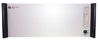
Master EMC Test Control Panel MCP-01
|
The TDK RF Solutions MCP-01 Master Control Panel is designed for EMC testing control rooms to provide interlock status, fiber optic links to remote locations or racks, and protection monitoring. |
|
Control of Remote Locations The interlocks from several remote racks can be daisy-chained together so that if any single rack is triggered the whole system will react. This gives you the flexibility of operating safely from any location within the system confines. Automatic or Manual Safety Features The interlock section of the MCP-01 contains automatic and manual controls for safety. In automatic mode, if the shielded room door is opened the LED will extinguish, alerting the user of a dangerous situation, while the amplifier inputs are automatically terminated into 50 Ohm input protection loads, which prevents them from radiating any fields into the shielded room. If the manual RF override switch is used, the LED will also extinguish itself. The RF override switch will also terminate the amplifier inputs into the 50 Ohm loads. The RF override switch interface allows the operator to physically force the amplifier input to a low level by "grounding" it to a 50 Ohm reference. Power Controls The MCP-01's primary power-on button consists of a backlit push panel indicator. It activates the main rack's power as well as any remote racks that might be on the fiber optic link. Multiple racks, in various locations, can be turned on or off from a single point. As with the safety features, the redundant on/off features are present on every rack, rear and remote, insuring that the operator can intervene with the system at any location. |
|
|
|
|
|
Amplifier Interface AI-1000
|
The TDK RF Solutions AI-1000 Interface operates as its own controller from direct IEEE-488 bus connection. The interface can also be operated manually via the from panel push button switches. |
|
Copyright © 2001- R. A. Mayes Company, Inc. An Electro Mechanical Research and Development (EMRAD) Corporation, Company See our Privacy Policy All the data files on our website require Adobe Acrobat Reader! |