|
|
|
|
|
|
|

|
|
|
|
|
|
|
|
|
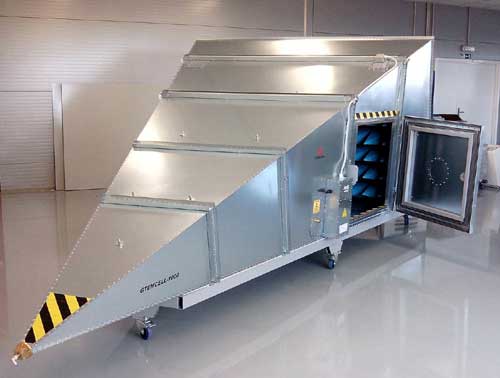
| GTEM Test Cells |
GTEM Italia |
|
|
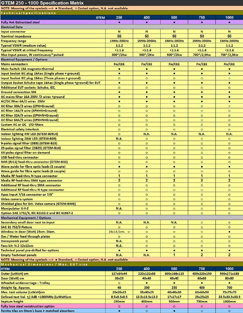
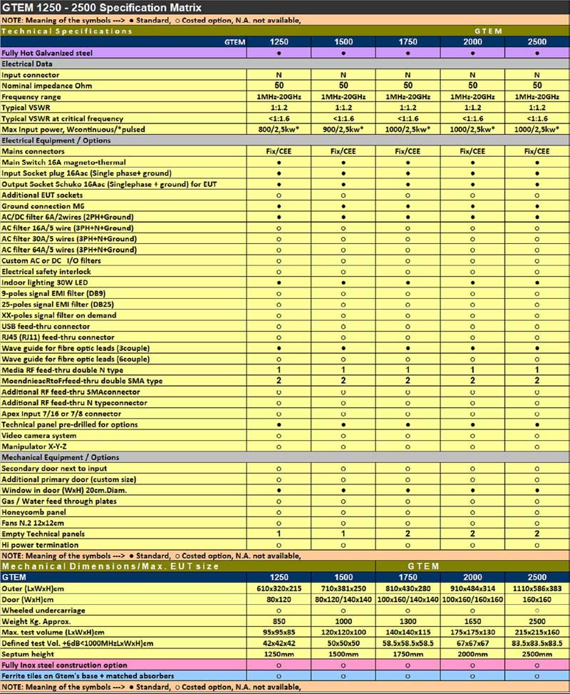
GTEM Test Cells for EMC Testing | |
|
DC - 20 GHz
|
The GTEM cell is a TEM waveguide with the upper frequency limit extended to the GHz range. It is a low-cost alternative measurement facility for both radiated emission and immunity measurements. It is included in the published standard IEC 61000-4-20 "Emission and Immunity Testing in Transverse Electromagnetic (TEM) Waveguides". Compared to other measuring methods like EMC test in anechoic chambers or OATS (Open Area Test Sites), GTEM Cells offer some significant advantages for the testing of small and medium sized EUT's (Equipment Under Test) up to a frequency range of 20GHz. Quick turnarounds of the EUT as well as numerous testing variations are easy and fast to handle. Switching from emission to immunity testing requires only simple adjustments, from receiver input to amplifier output.
You are irrespective of long waiting times associated with off-site test labs or weather and ambient delays that can occur at OATS facilities. Whether you are at the design qualification, pre-compliance, compliance, or production sampling stage, the GTEM is the right choice for you. |
|
|
|
|
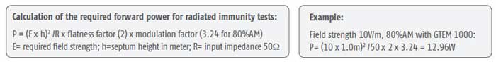
Power Requirements for Radiated
Immunity Testing XYZ EUT Manipulator for GTEM750 & Larger Advantages Over the Competitors GTEM |
|
|
|
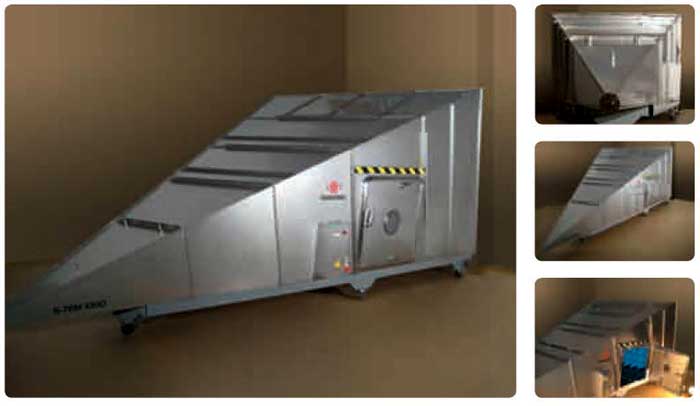
GTEM Test Cells acc. to IEC/EN 61000-4-20 |
|
|
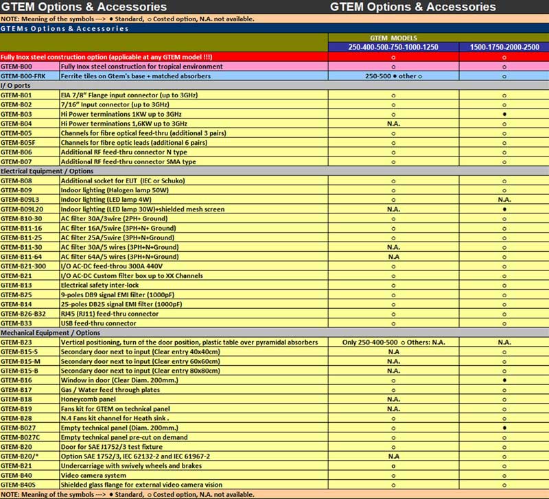
GTEM Test Cell Optional Accessories |
|
|
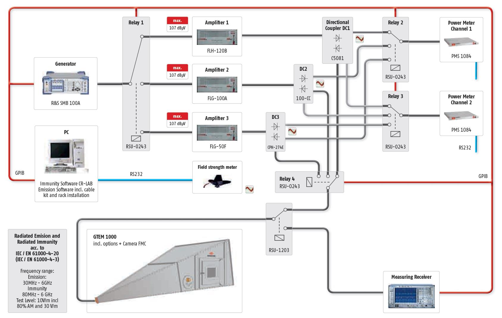
GTEM Set-up for
Radiated Immunity
|
|
 |
|
|
APPLICATION |
|
|
TEST METHODS RE01 and RE101 The Type 7334-1 Loop Antenna is positioned 7 cm from the face of the equipment under test with the plane of the loop parallel to the equipment face. The best position to begin with is opposite or near a joint or seam. The associated EMI meter is then scanned over the range 30 Hz to 100 KHz searching for emissions. At the frequencies where emissions are found, the loop antenna is moved about the surface seeking the strongest emission level. When a strong signal is detected, the loop is oriented on its axis for a maximum reading. This procedure is repeated for all surfaces of the equipment under test. Although the specification is not clear on the point, it appears to indicate that all six sides (including the bottom) of an equipment must be tested in this manner. When testing cables, the loop antenna is placed 7 cm from the cable with the plane of the loop parallel to the cable. The non-metallic base plate of the Type 7334-1 Loop Antenna provides a convenient means for establishing the correct 7 cm distance. | |
|
Copyright © 2001- R. A. Mayes Company, Inc. An Electro Mechanical Research and Development (EMRAD) Corporation, Company See our Privacy Policy All the data files on our website require Adobe Acrobat Reader! |