|
|
|
|
|
|
|

|
|
|
|
|
|
|
|
|
| Signal Generators |
 |
LAPLACE INSTRUMENTS
|
 |
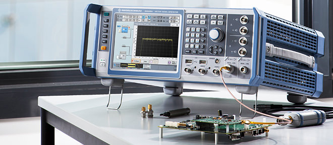
Rohde & Schwarz Signal Generators |
|
Vector signal generators, analog signal generators, baseband and modulation generators.
Baseband, RF and microwave signal generators from Rohde & Schwarz excel in signal quality, flexibility and usability. Rohde & Schwarz signal generators offer wide frequency ranges up to 67 GHz (up to 170 GHz with frequency multipliers), feature modulation bandwidths up to 2 GHz and support all major mobile communications and wireless digital standards. The portfolio ranges from ultra compact and fast analog and digital signal sources, optimized for use in production and automated solutions, to premium class vector signal generators with multichannel and fading simulation capabilities for most demanding applications.
R&S-SMW200A Vector Signal Generator The fine art of signal generation Frequency range 100 kHz to 3 GHz, 6 GHz, 12.75 GHz, 20 GHz 31,8 or 40 GHz Optional second RF path with 100 kHz to 3 GHz, 6 GHz, 12.75 GHz or 20 GHz Up to 2 GHz I/Q modulation bandwidth (in RF) with internal baseband Optional integrated fading simulator with up to 160 MHz bandwidth Support of all key MIMO modes including 3x3, 4x4 and 8x2
R&S-SMBV100B vector signal generator Vector Signal Generator, including ARB baseband generator (64 Msample, 120 MHz RF bandwidth) Frequency range from 8 kHz to 3 GHz or 6 GHz Ultra high output power up to +34 dBm 500 MHz modulation bandwidth with perfect accuracy
GNSS Simulator for the R&S-SMBV100A Vector Signal Generator The new reference in satellite simulation supports GPS, Glonass and Galileo Frequency based on the RF band and the GNSS hybrid configuration
R&S-SGT100A SGMA Vector RF Source Fast and compact solution & optimized for automated test environments 1 MHz to 3 GHz or 6 GHz Fastest and most compact vector RF source Integrated and powerful baseband with up to 240 MHz I/Q modulation bandwidth (in RF)
R&S-SGS100A SGMA RF Source Compact, Fast & Reliable 1 MHz to 6 GHz or 12.75 GHz for CW 80 MHz to 6 GHz or 12.75 GHz for vector mode Dedicated ATE signal source
R&S-SGU100A SGMA Upconverter Compact, Fast & Reliable 12 GHz to 40 GHz for CW 12 GHz to 40 GHz for vector mode Dedicated ATE signal source
R&S-SZU100A IQ Upconverter Wide band mmWave vector signal generation Center frequency from 58.32 GHz to 64.80 GHz
R&S-SMA100B RF and Microwave Signal Generator Performance leadership without compromise 8 kHz to 3 GHz, 6 GHz, 12.75 GHz, 20 GHz, 31.8 GHz, 40 GHz, 50 GHz or 67 GHz
R&S-SMF100A Microwave Signal Generator Top SSB phase noise performance, output power up to +23 dBm, sophisticated pulse modulation capabilities. 100 kHz to 22 GHz / 31.8 / 43.5 GHz
R&S-SMB100A Microwave Signal Generator Versatile, compact, up to 40 GHz; 170 GHz with upconverter 100 kHz to 12.75/20/31.8/40 GHz
R&S-SMB100B RF Signal Generator Perfect combination of performance and usability in a compact size 8 kHz to 1 GHz, 3 GHz or 6 GHz
R&S-SMC100A Signal Generator Smallest size and best price/performance ratio in its class 9 kHz to 1.1 GHz or 3.2 GHz
R&S-SGS100A SGMA RF Source Compact / fast / reliable 1 MHz to 6 GHz or 12.75 GHz for CW Dedicated ATE signal source
R&S-SGU100A SGMA Upconverter Compact / fast / reliable 12 GHz to 20 GHz for CW 12 GHz to 20 GHz for vector mode Dedicated ATE signal source
R&S-SMZ Frequency Multiplier Precise and adjustable output levels 50 GHz to 75 GHz, 60 GHz to 90 GHz, 75 GHz to 110 GHz, 110 GHz to 170 GHz
R&S-AFQ100B UWB Signal and I/Q Modulation Generator High performance baseband signals I/Q bandwidth: 264 MHz Broadband I/Q signals (528 MHz RF bandwidth) with up to 1Gsample memory for UWB and aerospace & defense applications.
R&S-AFQ100A I/Q Modulation Generator Meeting new challenges in baseband signal generation I/Q bandwidth: 100 MHz Outstanding signal quality
HMF2525/HMF2550 Arbitrary Function Generator Accurate, versatile and price convenient 10 μHz to 25 MHz or 50 MHz Arbitrary waveform generator: 250 Msample/s, 14 bit, 256 kpoint
HM8150 Arbitrary Function Generator Easy to use, multi-functional and a great price Frequency range: 10 MHz to 12.5 -Hz Arbitrary waveform generator 40 MSa/s
R&S-Pulse Sequencer Software A powerful radar signal simulation software Supported Instruments: R&S-SMW200A, R&S-SMBV100A, R&S-SMBV100B, R&S-SGT100A,
R&S-WinIQSIM2 Simulation Software Generation of digital I/Q signals according to various radio standards Supported instruments: R&S-AFQ100A, R&S-AFQ100B, R&S-SMU200A, R&S-SMJ100A, R&S-AMU200A, R&S-EX-IQ-Box, R&S-SMBV100A, R&S-CMW270, R&S-CMW280, R&S�CMW500, R&S-SMW200A, R&S-SGT100A
|
|
Copyright © 2001-2023 R. A. Mayes Company, Inc. An Electro Mechanical Research and Development (EMRAD) Corporation, Company See our Privacy Policy All the data files on our website require Adobe Acrobat Reader! |