|
|
|
|
|
|
|

|
|
|
|
|
|
|
|
|
| Wireless Antennas |
|
|
 |
Schwarzbeck Wireless Test Log Periodic Antennas |
|||||||||||||||||||||||||||||
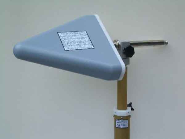
ESLP 9145 - Microwave Wireless Log Periodic Antenna |
|||||||||||||||||||||||||||||
|
1 - 18 GHz 700 MHz to 20 GHz Usable |
A new low attenuation cover allows measurements with radome.
|
||||||||||||||||||||||||||||
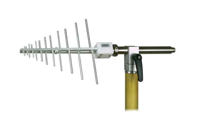
USLP 9143 B - Log Periodic Wireless Test Antenna |
|||||||||||||||||||||||||||||
  0.2 - 7 GHz 180 MHz to 8 GHz Usable |
|
||||||||||||||||||||||||||||
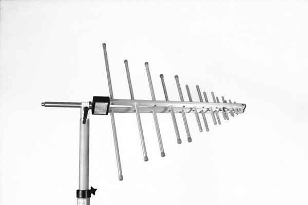
USLP 9142 - Schwarzbeck Log Periodic Wireless Test Antenna |
|||||||||||||||||||||||||||||
0.7 - 5 GHz |
|
||||||||||||||||||||||||||||
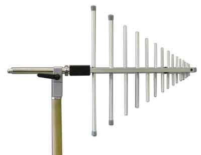
VUSLP 9111-1000 - Log Periodic Antenna |
|||||||||||||||||||||||||||||
0.8 - 3 GHz |
|
||||||||||||||||||||||||||||
VUSLP 9111-400 - Schwarzbeck Log Periodic Wireless Test Antenna |
|||||||||||||||||||||||||||||
0.4 - 3 GHz |
|
||||||||||||||||||||||||||||
|
|
|||||||||||||||||||||||||||||
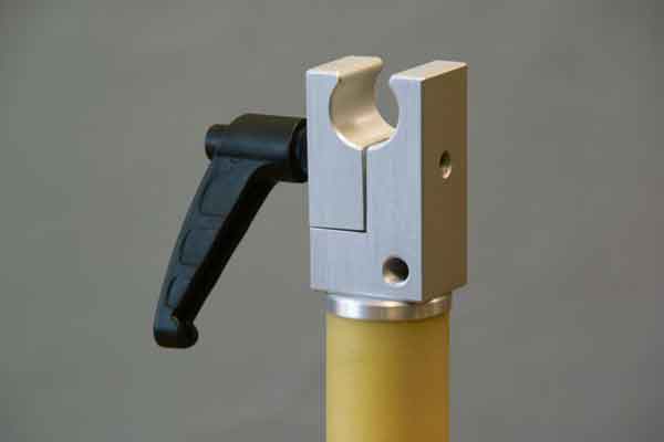
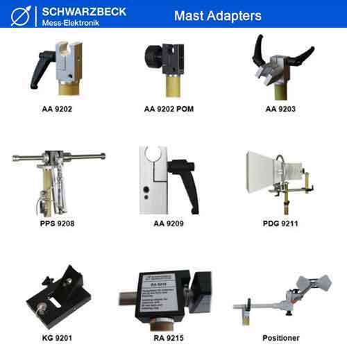
AA 9202
|
Mast Adapter for Antenna Mast System AM 9144 with 22 mm hole for most Antenna models. 3/8" and 1/4" camera threads polarization continuously adjustable
|
||||||||||||||||||||||||||||
|
|
|||||||||||||||||||||||||||||
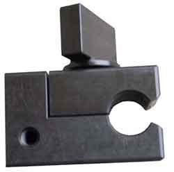
AA 9203
|
Mast Adapter for AM 9144 with 22 mm hole for most Antenna models 3/8" and 1/4" camera threads polarization and elevation continuously adjustable
|
||||||||||||||||||||||||||||
|
|
|||||||||||||||||||||||||||||
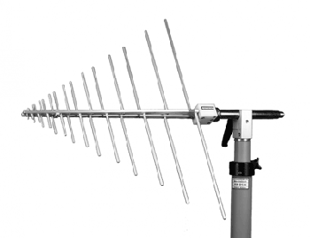
 The Log Periodic Dipole Antennas normally consists of a series of half wave dipole "elements" each consisting of a pair of metal rods, positioned along a support boom lying along the antenna axis. The elements are spaced at intervals following a logarithmic function of the frequency, known as d or sigma. The length of the successive elements and the spacing between them gradually decrease along the boom. The relationship between the lengths is a function known as tau. Sigma and tau are the key design elements of the LPDA design. The radiation pattern of the antenna is unidirectional, with the main lobe along the axis of the boom, off the end with the shortest elements. Each dipole element is resonant at a wavelength approximately equal to twice its length. The bandwidth of the antenna, the frequency range over which it has maximum gain, is approximately between the resonant frequencies of the longest and shortest element. The elements are equipped with soft plastic caps to avoid
injury and for optical reasons. Due to dielectric loss the soft plastic caps
are heating up when the antenna is dissipating around 500 W of power.
Occasionally the plastic caps get deformed or even damaged. |
|||||||||||||||||||||||||||||
|
Copyright © 2001- R. A. Mayes Company, Inc. An Electro Mechanical Research and Development (EMRAD) Corporation, Company See our Privacy Policy All the data files on our website require Adobe Acrobat Reader! |