|
|
|
|
|
|
|

|
|
|
|
|
|
|
|
|
| Pearson Current Monitors |
|
|
 |
|
|
|
|||
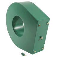
Wideband Current Monitors & Clamps |
||
|
|
||
|
Whether you are interested in observing and measuring submilliamp
currents in a charged particle beam or thousands of amps resulting from a
fault in a major power feeder, you will find a wideband Pearson current monitor or
clamp to
suit your needs. |
|
|
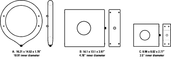
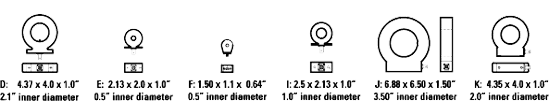
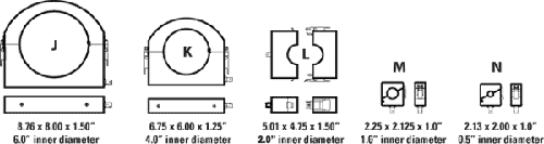
Shape |
Output |
Hole ID |
Time Domain Parameters |
Frequency Domain Parameters |
||||||
|
Max. amps |
Droop |
Rise nsec. |
IT Max. (amp-s) |
Max. |
3dB pt. |
3dB |
I/f |
||||
|
F |
1.0 |
0.25 |
100 |
200 |
2 |
0.0004** |
2.5 |
300 |
200 |
0.0025 |
|
|
E |
1.0 |
0.5 |
500 |
90 |
10 |
0.002** |
5 |
140 |
35 |
0.006 |
|
|
D |
1.0 |
2.0 |
500 |
80 |
20 |
0.005** |
7.5 |
125 |
20 |
0.017 |
|
|
K |
1.0 |
2.0 |
500 |
300 |
1.5 |
0.002** |
10 |
400 |
250 |
0.008 |
|
|
J |
1.0 |
3.5 |
500 |
140 |
3.5 |
0.01** |
10 |
200 |
120 |
0.04 |
|
|
C |
1.0 |
3.5 |
500 |
40 |
50 |
0.03** |
12 |
40 |
7 |
0.1 |
|
|
D |
0.5 |
2.0 |
1k |
20 |
20 |
0.02** |
15 |
40 |
20 |
0.07 |
|
|
K |
0.5 |
2.0 |
1k |
100 |
2.5 |
0.008** |
20 |
100 |
200 |
0.03 |
|
|
C |
0.25 |
3.5 |
2k |
100 |
30 |
0.09 |
60 |
160 |
10 |
0.6 |
|
|
F |
0.1 |
0.25 |
400 |
20 |
5 |
0.004** |
10 |
30 |
70 |
0.025 |
|
|
E |
0.1 |
0.5 |
5k |
60 |
20 |
0.25 |
50 |
120 |
20 |
1.7 |
|
|
E |
0.1 |
0.5 |
5k |
0.9 |
20 |
0.2** |
50 |
1 |
20 |
0.6 |
|
|
I |
0.1 |
1.0 |
5k |
1 |
20 |
0.2 |
50 |
1 |
20 |
0.6 |
|
|
D |
0.1 |
2.0 |
5k |
0.8 |
20 |
0.5** |
65 |
1 |
20 |
1.5 |
|
|
D |
0.1 |
2.0 |
10k |
0.8 |
20 |
0.5** |
65 |
1 |
20 |
1.5 |
|
|
K |
0.1 |
2.0 |
2k |
15 |
5 |
0.04** |
40 |
25 |
120 |
0.12 |
|
|
C |
0.1 |
3.5 |
5k |
20 |
40 |
0.6 |
140 |
40 |
10 |
3.6 |
|
|
A |
0.1 |
10.75 |
5k |
250 |
50 |
0.7** |
120 |
400 |
7 |
4.4 |
|
|
D |
0.025 |
2.0 |
20k |
100 |
100 |
0.5 |
100 |
160 |
4 |
3.0 |
|
|
C |
0.025 |
3.5 |
20k |
4 |
100 |
3.0 |
325 |
7 |
4 |
20.0 |
|
|
F |
0.01 |
0.25 |
2k |
2 |
20 |
0.04** |
25 |
3 |
20 |
0.25 |
|
|
E |
0.01 |
0.5 |
25k |
0.3 |
20 |
0.5** |
100 |
0.5 |
20 |
3.0 |
|
|
D |
0.01 |
2.0 |
50k |
0.1 |
100 |
2.5** |
200 |
0.25 |
4 |
12.0 |
|
|
D |
0.01 |
2.0 |
20k |
0.3 |
25 |
1.0** |
150 |
0.5 |
15 |
3.5 |
|
|
C |
0.01 |
3.5 |
50k |
3 |
200 |
22.0 |
400 |
5 |
2 |
140.0 |
|
|
C |
0.005 |
3.5 |
200k |
2.0 |
250 |
25 |
750 |
3.0 |
1.5 |
150 |
|
|
C |
0.005 |
3.5 |
100k |
1.0 |
250 |
65 |
1400 |
0.9 |
1.5 |
400 |
|
|
D |
0.001 |
2.0 |
200k |
0.05 |
200 |
6.0** |
400 |
0.7 |
2 |
40 |
|
|
C |
0.001 |
3.5 |
500k |
0.7 |
500 |
75 |
2500 |
1.0 |
1.2 |
450 |
|
|
B |
0.001 |
4.75 |
500k |
0.09 |
2000 |
1200 |
2500 |
0.15 |
0.2 |
7500 |
|
  Accuracy +1%, -0% of initial pulse amplitude for all models, with a high impedance load such as 1 megohm in parallel with 20 pF. A 50 ohm termination will reduce the output to half. * are
double shielded and are recommended for high voltage or high noise
environments. The entries labeled |
Pearson Clamp On Current Monitors |
||

|
||
|
Accuracy ±1% or better, initial pulse response for all models, with a
high impedance load such as 1 mΩ in parallel with 20 pF. |
|
|
|
|
|
Time Domain Parameters |
Frequency Domain Parameters |
|||||||
|
|
|
Useable |
|
Max. |
3dB |
3dB |
I/f |
I2t max |
||||
|
N |
1.0 |
0.5 |
500 |
1.0 |
2 |
0.003 |
5 |
1.5k |
200 |
0.01 |
5 |
|
|
N |
1.0 |
0.5 |
500 |
1.0 |
15 |
0.0015 |
5 |
1.5k |
25 |
0.008 |
150 |
|
|
M |
1.0 |
1.0 |
500 |
0.7 |
2.5 |
0.002 |
5 |
1k |
150 |
0.01 |
25 |
|
|
M |
1.0 |
1.0 |
500 |
1.0 |
15 |
0.002 |
5 |
1.5k |
25 |
0.01 |
150 |
|
|
L |
1.0 |
2.0 |
500 |
0.4 |
12 |
0.005 |
15 |
600 |
30 |
0.03 |
150 |
|
|
- |
1.0 |
2.0 |
15 |
4.0 |
1 |
.0006 |
4 |
1.5k |
400 |
.002 |
.02 |
|
|
K |
1.0 |
4.0 |
500 |
0.7 |
25 |
0.004 |
15 |
1k |
25 |
0.02 |
150 |
|
|
J |
1.0 |
6.0 |
500 |
0.5 |
50 |
0.005 |
20 |
750 |
7.0 |
0.03 |
350 |
|
|
L |
0.5 |
2.0 |
1k |
0.1 |
20 |
0.02 |
25 |
150 |
18 |
0.08 |
700 |
|
|
K |
0.5 |
4.0 |
1k |
0.1 |
30 |
0.02 |
30 |
150 |
12 |
0.08 |
700 |
|
|
N |
0.1 |
0.5 |
5k |
0.015 |
20 |
0.15 |
50 |
25 |
20 |
0.7 |
18k |
|
|
M |
0.1 |
1.0 |
5k |
0.015 |
25 |
0.15 |
60 |
25 |
15 |
0.8 |
18k |
|
|
L |
0.1 |
2.0 |
5k |
0.004 |
25 |
0.5 |
100 |
6.0 |
15 |
2.5 |
18k |
|
|
K |
0.1 |
4.0 |
5k |
0.007 |
50 |
0.4 |
150 |
10 |
7.0 |
2.0 |
18k |
|
|
J |
0.1 |
6.0 |
5k |
0.007 |
100 |
0.4 |
175 |
10 |
4.0 |
2.0 |
35k |
|
|
N |
0.01 |
0.5 |
50k |
0.005 |
150 |
1.0 |
150 |
7.5 |
3.0 |
4.2 |
250k |
|
|
M |
0.01 |
1.0 |
50k |
0.003 |
175 |
0.8 |
125 |
5.0 |
2.0 |
4.0 |
140k |
|
|
L |
0.01 |
2.0 |
50k |
0.001 |
200 |
2.5 |
300 |
1.5 |
2.0 |
15.0 |
1M |
|
|
K |
0.01 |
4.0 |
50k |
0.001 |
200 |
3.0 |
400 |
1.5 |
2.0 |
15.0 |
2M |
|
|
J |
0.01 |
6.0 |
50k |
0.001 |
250 |
3.0 |
400 |
1.5 |
1.5 |
12 |
2M |
|
|
L |
0.001 |
2.0 |
200k |
.00025 |
250 |
8.0 |
500 |
0.4 |
1.5 |
50 |
1M |
|
 Accuracy ±1%, initial pulse response for all models unless otherwise stated, with a high impedance load such as 1 megOhm in parallel with 20 pF. A 50Ω termination will reduce the output to half. Droop: For a flat top current pulse, the output voltage decays toward zero. Initially, the decay appears linear and the slope is referred to as the droop rate. Usable Rise Time: If the 10% to 90% rise time is greater than the specified usable rise time, initial overshoot will be less than 10% of the pulse amplitude. ǂ = Type N Connector |
Pearson Custom Current Monitors |
||
|
|
||
|
Accuracy ±1% or better, initial pulse response for all
models, with a high impedance load such as 1 megOhm in
parallel with 20 pF. |
STANDARD MODELS |
||||||||||||||||||||||||||||||||||||||||||||||||||||||||||||||||||||||||||||||||||||||||||||||||||||||||||||||||||||||||||||||||||||||||||||||||||||||||||||||||||||||||||||||||||||||||||||||||||||||||||||||||||||||||||||||||||||||||||||||||||||||||||||||||||||||||||||||||||||||||||||||||||||||||||||||||||||||||||||||||||||||||||||||||||||||||||||||||||||||||||||||||||||||||||||||||||||||||||||||||||||
| ||||||||||||||||||||||||||||||||||||||||||||||||||||||||||||||||||||||||||||||||||||||||||||||||||||||||||||||||||||||||||||||||||||||||||||||||||||||||||||||||||||||||||||||||||||||||||||||||||||||||||||||||||||||||||||||||||||||||||||||||||||||||||||||||||||||||||||||||||||||||||||||||||||||||||||||||||||||||||||||||||||||||||||||||||||||||||||||||||||||||||||||||||||||||||||||||||||||||||||||||||||
CURRENT CLAMPS |
||||||||||||||||||||||||||||||||||||||||||||||||||||||||||||||||||||||||||||||||||||||||||||||||||||||||||||||||||||||||||||||||||||||||||||
|
||||||||||||||||||||||||||||||||||||||||||||||||||||||||||||||||||||||||||||||||||||||||||||||||||||||||||||||||||||||||||||||||||||||||||||
DOUBLE SHIELDED CURRENT CLAMPS |
||||||||||||||||||||||||||||||||||||||||||||||||||||||||||||||||||||||||||||||||||||||||||||||||
|
||||||||||||||||||||||||||||||||||||||||||||||||||||||||||||||||||||||||||||||||||||||||||||||||
THIN CURRENT CLAMPS |
||||||||||||||||||||||||||||||||||||||||||||||||||||||||||||||||||||||||||||||||||||||||||||||||||||||||||||||||||||||
|
||||||||||||||||||||||||||||||||||||||||||||||||||||||||||||||||||||||||||||||||||||||||||||||||||||||||||||||||||||||
|
Accuracy ±1%, initial pulse response for all models unless otherwise stated, with a high impedance load such as 1 mΩ in parallel with 20 pF. A 50Ω termination will reduce the output to half. Droop: For a flat top current pulse, the output voltage declines toward zero. Initially, the decay appears linear and the slope is referred to as the droop rate. Usable Rise Time: If the 10 to 90% rise time is greater than the specified usable rise time, initial overshoot will be less than 10% of the pulse amplitude. ǂ = Type N Connector |
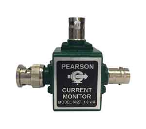
Pearson Coaxial Current Monitor |
|
Pearson Electronics introduces a new wide band current monitor that allows you to easily measure current within a coaxial cable system. The current monitor can be inserted within a coaxial cable run by means of two BNC connectors. |
 |
|
The Model 6027 has a 3dB bandwidth from 300 Hz to 200 MHz and an
rms current rating of 2.5 Amperes. |
|
Copyright © 2001- R. A. Mayes Company, Inc. An Electro Mechanical Research and Development (EMRAD) Corporation, Company See our Privacy Policy All the data files on our website require Adobe Acrobat Reader! |