|
|
|
|
|
|
|

|
|
|
|
|
|
|
|
|
| Solar LISN (New Style) |
.jpg) |
 |
|
FCC Line Impedance Stabilization Networks(New Design Housing) The F.C.C. in Part 15 Subpart Jhas adopted the 50 microhenry Line Impedance Stabilization Network (LISN)described in Figure 15 of the German Document VDE 0876/1/9.78 for use in performing conducted emission tests on power lines (10 KHz-30 MHz). (Five microhenry units are required for F.C.C. Part 18. See listing on back side of "LINE IMPEDANCE STABILIZATION NETWORKS" data sheet.) In selecting the appropriate LISN, the impedance-versus-frequency characteristic is the most important parameter to be considered. The impedance curve of the units closely matches the F.C.C. requirements.APPLICATION When measuring conducted radio interference voltages from active power lines to ground, it is essential to know the line impedance so that repeatable tests can be made by more than one laboratory. Artificial line impedances are specified in MIL-STD-462, FCC, VDE, CISPR, C22.4, NACSEM 5100, ANSI C63.2 and other EMI specifications. The characteristic impedance of the 5 µH and 50 µH LISNs brackets the mean value of power line impedance which has been measured by independent researchers. These two inductance values in parallel with the 50 ohms of the EMI meter fall between the minimum and maximum line impedance values which have been measured. The mean value would be represented by a 20 µH inductor in parallel with 100 ohms.
|
|
DESCRIPTION The Solar Electronics LISNs - Line Impedance Stabilization Network use a series inductor between the test sample and the power source to provide the impedance-versus frequency characteristic. A coaxial connector with D.C. isolation use a series inductor between the test sample and the power source to provide the impedance-versus frequency characteristic. A coaxial connector with D.C. isolation use a series inductor between the test sample and the power source to provide the impedance-versus frequency characteristic. A coaxial connector with D.C. isolation is provided for connection to the associated frequency selective EMI meter. The power source end of the inductor is bypassed to ground. Due to the large current-carrying capability of some LISNs, it is not always practical to use a switch for changing inductance values. Instead, some models are equipped with a high current pin plug-and-jack combination for quickly connecting and disconnecting a network and substituting another. This nylon insulated pin plug and jack arrangement is a safety feature, well isolated from inadvertent short circuits, providing protection to operating personnel. Current ratings up to 200 amperes are available in 50 µH styles and 500 amperes in 5 µH styles. When measurements are made in a shielded room, the LISNs intended for FCC applications will also serve for VDE tests. When operating on an unfiltered power line, the VDE specifications require a filter consisting of 250 µH inductor and a capacitor. This filter is included in the 24 ampere LISN, Type 9348-50-R-24-BNC, and the 50 ampere LISN, Type 8602-50-TS-50-N.
EMI specifications require one LISN in each ungrounded power lead. |
| Single line units are needed in each power lead. Use two for single phase or d.c. systems Three for delta connected three-phase lines Four for Wye connected three-phase lines. 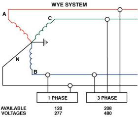 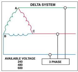 |
|
Specification |
Inductance |
Frequency Range |
|
FCC Part 15 |
50 µH |
10 kHz - 30 MHz |
|
FCC Part 18 |
5 µH or 50 µH |
10 kHz - 30 MHz |
|
CISPR-16 |
50 µH |
Band A for 9 kHz to 150 kHz and Band B for 150 kHz to 30 MHz |
|
CISPR-25 |
5μH |
100 kHz - 100 MHz |
|
VDE 0876-16-1-2 |
50 µH |
9 kHz - 100 MHz with 250 �H choke |
|
MIL-STD 461/462 Rev C |
57 µH |
10 kHz - 10 MHz, 14 kHz - 4 MHz |
|
MIL-STD 461/462 Rev C |
5 µH |
100 kHz - 100 MHz |
|
MIL-STD 461/462 Rev D |
50 µH |
150 kHz - 100 MHz with 10 pF capacitor |
|
RTCA DO-160 |
5 µH |
100 kHz - 400 MHz |
|
SAE J1113 |
5 µH |
150 kHz - 65 MHz |
|
TEMPEST |
5 µH |
100 kHz - 1,000 MHz |
|
SOLAR Line Impedance Stabilization Networks (New Style) |
|
CISPR 16-1-2, CISPR 22, FCC, ANSI C63.4 |
|||||||
|
Type Number |
Inductance µH |
Current
Amps |
Line/Ground Voltage 50-60 Hz |
Line/Ground Voltage 400 Hz |
Case Size* |
Circuit |
Frequency Range |
|
21105-50-bp-10-bnc |
50 | 10 | 270 | 135 |
#1 |
Single |
150 KHz- 30 MHz |
|
21106-50-bp-25-bnc |
50 | 25 | 270 | 135 |
#1 |
Single |
150 KHz- 30 MHz |
|
21107-50-ts-50-n |
50 | 50 | 270 | 135 |
#3 |
Single |
150 KHz- 30 MHz |
|
21107-50-pj-50-n |
50 | 50 | 270 | 135 |
#3 |
Single |
150 KHz- 30 MHz |
|
21108-50-ts-100-n |
50 | 100 | 270 | 135 |
#3ǂ |
Single |
150 KHz- 30 MHz |
|
21108-50-pj-100-n |
50 | 100 | 270 | 135 |
#3ǂ |
Single |
150 KHz- 30 MHz |
|
21114-50-ts-50-n |
50 | 50 | 500 | 240 |
#3 |
Single |
150 KHz- 30 MHz |
|
21114-50-pj-50-n |
50 | 50 | 500 | 240 |
#3 |
Single |
150 KHz- 30 MHz |
|
21114-50-ts-100-n |
50 | 100 | 500 | 240 |
#3ǂ |
Single |
150 KHz- 30 MHz |
|
21114-50-pj-100-n |
50 | 100 | 500 | 240 |
#3ǂ |
Single |
150 KHz- 30 MHz |
|
ǂ |
With 50 or 60 Hz Ventilating Fan; add 7.09" (18.00 cm) |
|
|
Add 3" (7.62 cm) for Base Plate |
|
*Case Sizes |
Width x Height x Length |
|
#1: |
4.5" x 4.5" x 9.25" (11.43 cm x 11.43 cm x 23.5 cm) |
|
#2: |
7.0" x 7.0" x 8.25" (17.78 cm x 11.78 cm x 24.13 cm) |
|
#3: |
10.06" x 9.0" x 13.12" (25.72 cm x 22.86 cm x 33.34 cm) |
|
#4: |
7.53" x 7.63" x 18.97" (19 cm x 19.43 cm x 48.26 cm) |
|
#5: |
3.12" x 1.75" x 3.87" (7.94 cm x 4.44 cm x 9.84 cm) |
|
#6: |
2.75" x 2.45" x 5.7" (6.98 cm x 6.22 cm x 14.48 cm) |
|
#7: |
13.06" x 7.0" x 10.06" (33.20 cm x 17.78 cm x 25.55 cm) |
|
Note: Unless otherwise specified, 5μH LISN's have 0.1pf coupling caps; 50μH have 0.25pf coupling caps |
|
|
Copyright © 2001- R. A. Mayes Company, Inc. An Electro Mechanical Research and Development (EMRAD) Corporation, Company See our Privacy Policy All the data files on our website require Adobe Acrobat Reader! |