Translate The Website (Starts on Home Page)    
RA Mayes EMC Test
Follow Us On LinkedIn   Twitter   facebook
R A Mayes Logo and Home Page Call Nationwide 1-800-742-9447


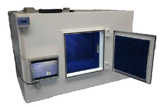
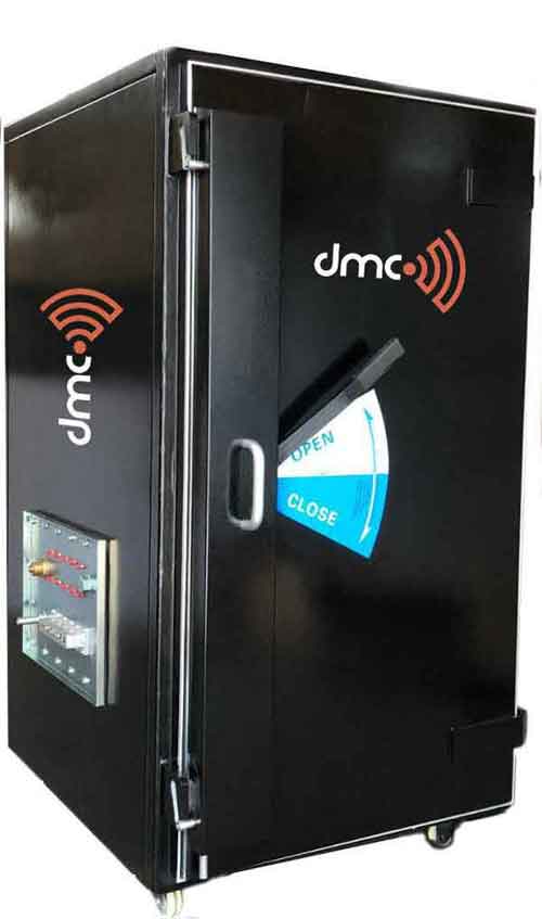
Portable Wireless Test Chambers
Keysight Partner

DMC Logo

Made in Canada

DMC OTA Testing Sub 6GHz Portable Wireless Test Chamber

DMC-OTA-S6

The DMC-OTA-S6 series RF shielded enclosures are cost-effective for over-the-air (OTA) testing at 6GHz.

Our advanced shielding technology provides high isolation level make them suitable for OTA mmwave testing.


DMC-OTA-6G Test Chamber

DMC-OTA-6G Wireless Test Chamber


To minimise path loss and to get best results, these shield boxes can include racking options to incorporate instruments directly at the enclosure.
  • Frequency 700MHz to 6GHz
  • Shielding effectiveness > 70dB
  • 4 DUTs test in parallel
  • High efficient acquisition algorithm for processing the TRP with multiple test probes, instead of adjusting the antenna position by products. Achieve ±1dB accuracy
  • Support TX, RSSI, BER, BLER,FER, EVM, RSE and other test indicators
  • Wireless communication with DUT. Avoid the USB impact to the antenna frequency response
  • Manual or RS-232C/remote operation, suitable for automation line;
  • Input AC power: 100-240V AC 50Hz.

Data

Technical Specification

Chamber Type

DMC-OTA-S6

Operation Mechanism

Manual  Operation

Outer Dimension (Cabinet)

660 W x 1113 D x 1960 H mm

Outer Dimension (Box)

660 W x 600 D x 1000 H mm

Internal Dimension(Box)

560 W x 830 D x 594 H mm

Door Opening  Dimension(Cabinet)

660 W x 1513 D x 1960 H mm

Door Dimension

407 W x 115 H mm

Open-close Mechanism

Pneumatic control

Color

Black/White or Custom

Weight

203kg


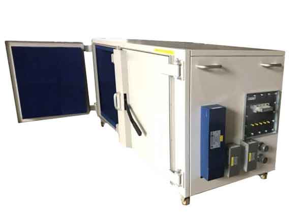
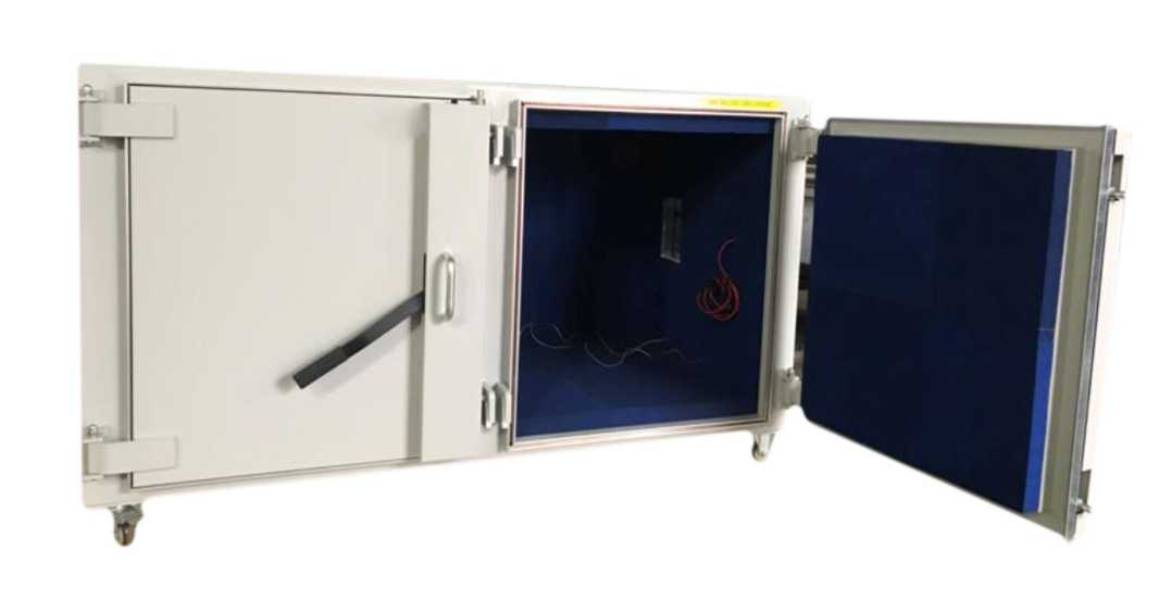
Dual 5G OTA Testing Portable mmWave Test Chamber

DMC-OTA-DUAL
The DMC-OTA-DUAL series RF shielded anechoic enclosures are cost-effective solutions for OTA testing for mmWave applications with two internally isolated compartments.
Lower section is ideal for placing test equipment such as spectrum analyser, VNA, signal source, RF switching, etc.
Our advanced shielding technology provides high isolation level make them suitable for testing 5G applications such as low-frequency devices (below 1 GHz) LTE-AP 5G-NR, and mmWave (FR1 and FR2).


Dual mmWaave Test Chamber

Dual OTA Test Chamber

Data


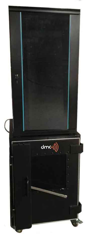
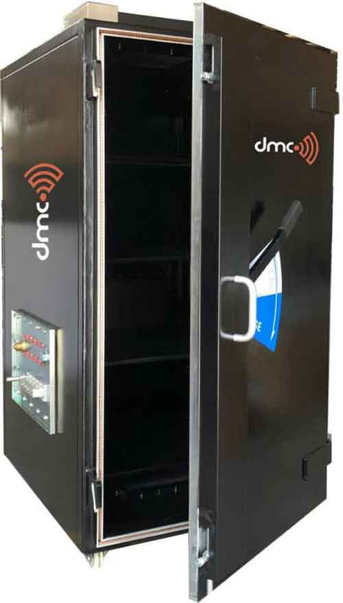
Typical Specifications

Chamber Type : DMC-RFE-OTA-DUAL

300MHz-40GHz

External dimension 850mm(W) x 950mm(L) x 1200mm(H)

Shielding effectiveness: >80dB

Wireless communication with DUT

EMI filter on all data lines

Manual or RS-232C/remote operation, suitable for automation line

Input AC power: 100-240V AC 50Hz.


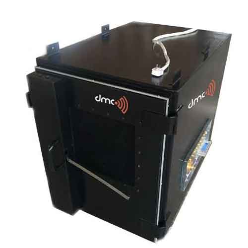
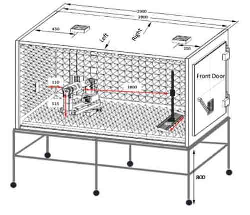
5G Millimeter Wave (mmwave) RF Shielded Test Chamber

DMC-5G-mmW

The DMC-5G-mmW series Millimeter wave RF shielded enclosures are advanced and compact direct field OTA test enclosure occupying minimal floor space. 100 mm thick high performance microwave absorber is fully lined on all walls, ceiling and floor.
These enclosures can be used for 5G small cell, Pico cells, Femto and Microcell near field and far field measurements.


5G OTA Test Chamber 


5G mmwave OTA Test Chamber 


OTA 5G Test Chamber


Features

  • Product: DMC Millimeter Wave RF Shielded Enclosure
  • Frequency range: 20 GHz to 40 GHz
  • Shielding Effectiveness : >70dB
  • Inside shield to shield dimension: 2900 mm (L) x 1450 (W) x 1450 (H)
  • RF shielded door: 1200 mm x 1200 mm, 2 doors
  • RF shielded door location: On DUT end and transmitting antenna end
  • Absorber Height: 100 mm
  • Positioner center location from Absorber tip: 560 mm
  • Positioner clearance radius required for 360° rotation: 457 mm
  • DUT to Horn antenna distance: 1800 mm
  • Honeycomb vent: 200 mm x 200 mm (on both doors)
  • Fan: On ceiling- 2 nos, On side wall- 2 nos
  • I/O panels: 4 nos on DUT side and 2 nos on Horn antenna side
  • Feed through panel for positioner: 200 mm x 200 mm

Data

Technical Specification of Shielded Enclosure with 5 Axis Positioner

OTA 5G Test Chamber Drawing
Positioner Details
 
Footprint: 12" x 12" (304 mm x 304 mm)
Total Height: 22.5" (571.5 mm)
Clearance Radius: 18" (914 mm) clearance radius required for full 360° rotation
Total Weight: 42 lbs (19 kg)

Positioner  & Turntable (theta)
 
Frequency Ranges (GHz): Coax: DC to 6, 18, 40, 50, or 67 GHz
mmW: 50-75 (V-Band), 60-90 (E-Band) or 75-110 (W-Band) GHz
Resolution: 0.02° full step
0.00125° microstep
Drivetrain: 3.0A/phase bipolar stepper motor with worm drive
Holding Torque: 25 ft-lb
Movement Range: 360° continuous or indexed
Position Feedback: 800-line encoder
Limits: Home & Limit (hardware & software)
Weight (positioner only): 16 lbs (7.27 kg)
Positioner Max Speed: 24" per second
AUT Mounting Options: 3/8"-16 or M6 4-hole pattern for general mounting
Composition: Acrylic turntable with aluminum base
Weight Capacity: 100 lbs (45 kg)
RF Rotary Joint: Optional (SMA, 2.92 mm, 2.4 mm, 1.85 mm or waveguide)

Gimbal (phi)
 
Frequency Ranges: Coax: DC to 6, 18, 40, 50, or 67 GHz
mmW: 50-75 (V-Band), 60-90 (E-Band) or 75-110 (W-Band) GHz
Resolution: 0.05° full step
0.00250° microstep
Drivetrain: 2.0A/phase bipolar stepper motor with belt drive
Holding Torque: 20 ft-lb
Movement Range: 360° continuous or indexed
Position Feedback: 800-line Encoder
Limits: Home (hardware & software)
Weight (gimbal only): 26 lbs (11.7 kg)
Gimbal Max Speed: 24" per second
AUT Mounting Options: 3.625" (92 mm) diameter PVC mounting plate with 10-32 hole array
Composition: Delrin, ABS, PLA+, fiberglass
Weight Capacity: 40 lbs (18 kg)
RF Rotary Joint: Optional (SMA, 2.92 mm, 2.4 mm, 1.85 mm or waveguide)

= Custom mounting solutions available upon request


Electrical & Communications
 
Controller type: 3 axis microprocessor based controller
Resolution: Full step through 1/32 microstep
Motor Current: 3.125A per motor phase max
Cooling: Dual 40mm 24V fans
Motor Connector: M12 axial 5-pin connector + 5-pin encoder connector
Communication Interface: DB9 RS232 serial port with external USB adapter
Communication cable length: 1 meter
Input Voltage: 24VDC 3A
Power Supply (included): 24VDC 5A & 110/220v input
Motor cable length: 1 meter


Copyright © 2001-2023  R. A. Mayes Company, Inc.
An Electro Mechanical Research and Development (EMRAD) Corporation, Company

See our Privacy Policy    All the data files on our website require Adobe Acrobat Reader!