|
|
|
|
|
|
|

|
|
|
|
|
|
|
|
|
| Ophir Conducted EMC Test |
|
|
|
|
|
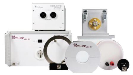
Ophir EMC Has Been Discontinued, Crossovers Are Available OPHIRRF, long known for manufacturing top quality, high power, solid state, broadband and band-specific RF amplifiers for over 20 years has expanded its product line with the creation of its newest division, OPHIREMC. OPHIREMC specializes in products for making EMI/EMC measurements. OPHIREMC extensive line of products include Line Impedance Stabilization Networks (LISN's), Current Probes, Injection Probes, Transient Generators, Transformers, Loops and Coupling/Decoupling Networks (CDN's). The EMC line is continuously expanding. Contact us for the latest product updates and information. The OPHIREMC product line offers the same outstanding quality, performance and service you have come to expect from OPHIRRF. OPHIR is ISO: 9001:2008 Registered with TUV Rheinland. |
||
Ophir EMC Test Products |
|||||||||||||||||||||||||||||||||||||||||||||
| |
|||||||||||||||||||||||||||||||||||||||||||||
| Military | Commercial | ||||||||||||||||||||||||||||||||||||||||||||
| Mil-Std-461F/461G Product List | EMC Product Overview | ||||||||||||||||||||||||||||||||||||||||||||
| RTCA DO-160G Preliminary Product List | EMC Products Listings | ||||||||||||||||||||||||||||||||||||||||||||
| DEF-STD-59-411 Product List | |||||||||||||||||||||||||||||||||||||||||||||
|
|
|||||||||||||||||||||||||||||||||||||||||||||
CISPR 16-1-2 Line Impedance Stabilization Network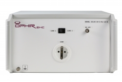 |
OPHIR EMC
offers a wide selection of Line Impedance Stabilization
Networks (LISN's) also referred to as Artificial Mains Networks for
CISPR 16-1-2 compliance testing requirements. LISN's also meet suitable for CISPR 22, CISPR 15, ANSI 63.4 and other EMC specifications. LISN's are available in three and four circuit configurations. Additional current and voltage ratings are available. |
||||||||||||||||||||||||||||||||||||||||||||
|
|
|||||||||||||||||||||||||||||||||||||||||||||
Mil-Std-461F/G Line Impedance Stabilization Network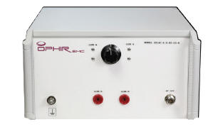 |
OPHIR EMC
manufactures a wide selection of Line Impedance
Stabilization Networks (LISN's) for pre-compliance and compliance
conducted emissions testing in accordance with various EMC standards.
The 2014M series of LISN's meet the requirements of Mil-Std-461F and 461G as well as earlier versions of the specification. The 2114D series meet the requirement for a 5μH LISN as specified in Appendix A of Mil-Std-461F/G. Additionally, the 2114D series of LISN are compliant with RTCA DO-160G when used with an external 10μF capacitor. LISN's are available in three and four circuit configurations. Additional current and voltage ratings are available. |
||||||||||||||||||||||||||||||||||||||||||||
|
|
|||||||||||||||||||||||||||||||||||||||||||||
RTCA-DO-160G Line Impedance Stabilization Networks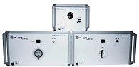 |
OPHIR EMC
2114D series and 2514D series of Line Impedance
Stabilization Networks (LISN's) are designed to meet the requirements of
commercial aviation specification RTCA-DO-160G. The 2114D series require the use of an external 10μF capacitor for DO-160 applications. The 2514D series LISN include the 10μF capacitor internally and additionally meets the requirements of Def-Std 59-411 and Euro Fighter specifications. 2114D series of LISN's is complaint with the requirements for optional 5 μH LISN as specified in Mil-Std-461F/G Appendix A. LISN's are available in three and four circuit configurations. Additional current and voltage ratings are available. |
||||||||||||||||||||||||||||||||||||||||||||
|
|
|||||||||||||||||||||||||||||||||||||||||||||
Line Impedance Stabilization Networks for Automotive Specifications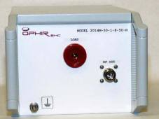 |
OPHIR EMC
2414I and 2314C series Line Impedance Stabilization
Networks (LISN's) are designed for vehicular conducted emissions testing
in accordance with ISO-7637-2, CISPR 25 and various automotive EMC
standards. The 2314C series includes a measurement port and 1μF as specified in CISPR 25. 2414I series is compliant with ISO-7637-2. Additional current and voltage ratings are available. |
||||||||||||||||||||||||||||||||||||||||||||
Current and Injection Probe Product List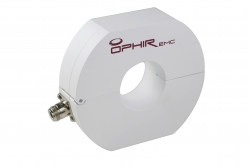 |
OPHIR EMC is developing an extensive line of Current and Injection Probes for various EMC standards such as Mil-Std-461, RTCA DO-160 and others. The Current Probes cover the frequency range of 20 Hz to 1 GHz. The Injection Probes frequency range coverage is 10 KHz to 1GHz. Probe Calibration Fixtures are also available. OCP212 Current Probe, 1MHz-1GHz, 32mm window |
||||||||||||||||||||||||||||||||||||||||||||
 |
CALIBRATION FIXTURES OFC120 BCI Calibration Fixture, 20Hz-500MHz, 10" x 7" x 6" OFC121 BCI Calibration Fixture, 100kHz-1GHz, 10" x 7" x 7" OFC123 BCI Calibration Fixture, 10kHz-400MHz, 12" x 7" x 7" OFC403 Dual Wide Calibration Fixture, 10kHz-400MHz, 6.5" x 6" x 6.5" |
||||||||||||||||||||||||||||||||||||||||||||
Induced Lightning System MIL-STD-461G & CS117 |
The OPHIREMC
OTG117 Induced Lightning System is a two part
system designed to cover the latest edition of Mil-Std-461G, CS117
consisting of OTG117.1 Multiple Stroke Generator covering Waveform 1-2
and 4-5 and OTG117.2 Multiple Stroke/Burse Generator covering Waveform 3
and 4. Cables and Probes/cores included with system. The OTG117.1 generator is capable of producing Current Waveform 1, Voltage Waveform 2 or Voltage Waveform 4, and Current Waveform 5A all in the Multiple Stroke format. Single event triggering is also available for engineering testing and level setting. It can produce these Waveforms at both the Internal and External Equipment Levels (see Table 1). The OTG117.2 generator is capable of producing Waveform 3 (1MHz & 10MHz) Multiple Stroke and Multiple Burst, as well as Waveform 6 Multiple Burst. Single event triggering is also available for engineering testing and level setting. It can produce these Waveforms at both the Internal and External Equipment Levels (see Table 2). |
||||||||||||||||||||||||||||||||||||||||||||
|
|||||||||||||||||||||||||||||||||||||||||||||
|
|
|||||||||||||||||||||||||||||||||||||||||||||
Model OCT101 Audio Coupling Transformer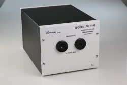 |
OPHIR EMC Model OCT101 Audio Coupling Transformer designed for making conducted audio frequency susceptibility tests as required by Mil-Std-461F/G and various automotive and aviation EMI specifications. Transformer is CE certified. | ||||||||||||||||||||||||||||||||||||||||||||
|
|
|||||||||||||||||||||||||||||||||||||||||||||
Model OLS110 Loop Sensor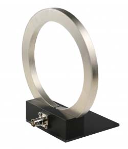 |
Model OLS110 Loop Sensor was designed to meet the requirements of MilStd-461E/F/G RE101 for the measurements of radiated magnetic field emissions from 30 Hz to 100 kHz. Model OLS110 is also used for radiated susceptibility testing as specified in RS101 alternative test procedure using AC Helmholtz coil. The Model OLS110 meets the requirements for compliance testing of other specifications and standards. Specifications Frequency Range: 20 Hz to 100 kHz Connector: Type BNC female Coil Diameter: 13.3 cm (5.24") Turns: 36 Wire: #7-41 Litz wire DC Resistance: Approximately 10 ohms Shielding: Electrostatic |
||||||||||||||||||||||||||||||||||||||||||||
|
|
|||||||||||||||||||||||||||||||||||||||||||||
| Model OPG115 Pulse Generator |
OPHIR EMC Model OPG115 Pulse Generator is designed to meet the requirements for CS115 susceptibility testing as specified in Mil-Std-461F/G. The Model OPG115 is used to provide pulse excitation on interconnecting cables through an injection probe. The Model OPG115 uses a coaxial charge line to generate a >30 ηS pulse with rise and fall time of less than 2 ηS. Pulse polarity reversible. Charge voltage displayed on front panel. Generator is capable of being computer controlled. Specifications Charge Voltage: 0-2000 volts Repetition Rates: 01-50 p.p.s. Pulse Rise and Fall Times: < 2 ηS Pulse Duration: >30 ηS Output Impedance: 50 Ω Output Connector Type N Power: 115V/230V, 50/60Hz |
||||||||||||||||||||||||||||||||||||||||||||
|
|
|||||||||||||||||||||||||||||||||||||||||||||
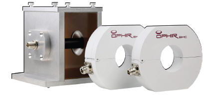
|
Model ORL110 Radiating Loop and Model OLS112 Loop Sensor 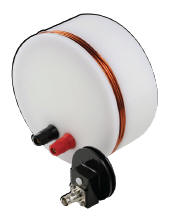 |
OPHIR EMC Model ORL110 Radiating Loop and Model OLS112 Loop Sensor are designed to meet the requirements for radiated magnetic field susceptibility testing from 30 Hz to 100 kHz as specified in Mil-Std-461F/G for RS101 testing. The ORL110 Radiating Loop is used in conjunction with the OLS112 Loop Sensor to verify the magnetic field generated by the ORL110 as required by RS101 of Mil-Std-461F/G. The ORL110 coil form positions the coil 5 cm from the EUT when placed against the EUT. The loops are also compliant with other EMC standards and specifications. ORL110 Radiating Loop Coil Diameter: 12 cm (4.72") Overall Dimensions: 13.3 cm (5.25") O.D. x 6 cm (2.37") Termination: Standard Binding Post Turns: 20 Wire: #12 insulated Copper Magnet Wire Magnetic Flux Density: 9.5x10⁷ pT/ampere of applied current at a distance of 5 cm from the plane of the loop. OLS112 Loop Sensor Coil Diameter: 4 cm (1.57") Overall Dimensions: 5 cm (2") O.D. x 1.9 cm (.749") Connector: Type BNC Receptacle Turns: 51 Wire: #7-41 Litz wire Shielding: Electrostatic |
||||||||||||||||||||||||||||||||||||||||||||
|
|
|||||||||||||||||||||||||||||||||||||||||||||
| Model OTG116 Sinusoidal Damping Transient Generator |
Model OTG116 Sinusoidal Damping Transient Generator is specifically designed to provide the damped sinusoidal pulses required by Mil-Std-461F/G section CS116. The Model OTG116 provides the six required frequencies as specified in MilStd-461F/G section CS116 through a single output. The Model OTG116 is capable of single pulse, auto pulsing of one frequency or all frequencies. The pulse rate is adjustable from 0.5 to 1 pulse per second. Open Loop Voltage is displayed for each frequency being tested. Generator can be externally control via computer interface. Specifications Frequencies: 10 kHz, 100 kHz, 1 MHz, 10 MHz, 30 MHz, 100 MHz Output Impedance: ≤ 100 ohms Output Current: 0.1 to 10 Amperes (depending on frequency) Damping Factor (Q): 15 - 5 Repetition Rate: Single, 0.5 p.p.s.-1.0 p.p.s. Power: 115V/230V, 50/60Hz Dimensions: 19" wide x 5.21" high x 20" |
||||||||||||||||||||||||||||||||||||||||||||
|
|
|||||||||||||||||||||||||||||||||||||||||||||
| Model OTG116A Sinusoidal Damping Transient Generator |
Model OTG116A
Sinusoidal Damping Transient Generator is
especially designed for the performance of a variety of pulse
susceptibility tests on subsystems and/or equipment, in accordance with
Mil-Std-461E/F/G section CS116. The Model OTG116A provides the six required damped sinusoidal frequencies as specified in Mil-Std-461G section CS116 through six individual outputs. The Model OTG116A is capable of a single pulse or auto pulsing of each of the frequencies at a pulse rate of 1 p.p.s. Open Loop Voltage is displayed for each frequency being tested. Specifications: Frequencies: 10 kHz, 100 kHz, 1 MHz, 10 MHz, 30 MHz, 100 MHz Output Impedance: ≤ 100 ohmsOutput Current: 0.1 to 10 Amperes (depending on frequency) Damping Factor (Q): 15 � 5 Repetition Rate: Single, 1.0 p.p.s. Power: 115V/230V, 50/60Hz Dimensions: 19" wide x 5.21" high x 20" |
||||||||||||||||||||||||||||||||||||||||||||
|
|
|||||||||||||||||||||||||||||||||||||||||||||
| Model OAA101 Audio Power Amplifier |
Model OAA101 Audio Power Amplifier is
designed for conducted susceptibility testing as specified in EMC
standard Mil-Std-461, RTCA DO-160 and additional EMC specifications. The
Audio Amplifier is used in conjunction with OPHIREMC
Model OCT101 Coupling Transformer. The Model
OAA101 provides a DC to 300 kHz bandwidth and up to 1000 watts power.
Amplifier has protection circuitry from input overloads, improper
outputs (including shorted and improper loads), over-temperature,
over-currents and over-voltages. There is a Digital Voltmeter display on
the front panel along with LED's displaying ready, over-temperature,
over-voltage and over load conditions. Forced air cooling. Capable of
being computer controlled. Designed to stand alone or be rack mounted.
Specifications Frequency Range: DC to 300 kHz Output Power: 1000 W atts AC Input Power: 115/230 V, 50/60 Hz Input Signal: 0.5-2.0 Volts RMS Input Impedance: 50 Ohms Output Impedance: 2.0 Ohms Output Voltage: >40 V RMS, 0-150 kHz Distortion: DC Drift: >=1.5 mV (after 30 minutes of operation) Phase Response: ±5 degrees Residual Noise: 300 μV Signal-to Noise Ratio: -100 dB Voltage Gain: 20 volts/volts Gain Linearity: Common Mode Rejection: -60dB with 5 v input Input Connector: Type BNC Output Connections: Standard Binding Post (or barrier strip)
|
||||||||||||||||||||||||||||||||||||||||||||
|
|
|||||||||||||||||||||||||||||||||||||||||||||
| Model OPA101 Audio Amplifier |
Model OPA101 Audio Power Amplifier
is designed for conducted susceptibility testing as specified in EMC
standard Mil-Std-461, RTCA DO-160 and additional EMC specifications. The
Audio Amplifier is used in conjunction with OPHIREMC Model OCT101
Coupling Transformer. The Model OPA101 provides a DC to 300 kHz
bandwidth and up to 200 watts power (225 watts into 1 ohm). Amplifier
has protection circuitry from input overloads, improper outputs
(including shorted and improper loads), over-temperature, and
over-currents. There is a Digital Voltmeter display on the front panel
along with LED's displaying ready, over-temperature, and over load
conditions. Forced air cooling. Designed to stand alone or be rack
mounted. 0.5 ohm data on chart taken with OTC101 Coupling Transformer
attached.
Specifications Frequency Range: DC to 300 kHz Output Power: 200 Watts @ 1kHz AC Input Power: 115/230 V, 50/60 Hz Input Signal: +0dBm Max. Input Impedance: 50 Ohms Output Impedance: 1.0 ohm, 2.0 Ohms Output Voltage: >10 V RMS, 0-150 kHz with +0dBm input Distortion: ≤ 0.3% DC Drift: >=1.5 mV (after 30 minutes of operation) Phase Response: ±5 degrees Residual Noise: 300 μV Signal-to Noise Ratio: -100 dB Gain Linearity: 0.15% Common Mode Rejection: -60dB Input Connector: Type BNC Output Connections: Standard Binding Post (or barrier strip) Size: 131mm (5.2") x 465mm (18.3") x 398mm (15.7") Weight: 55 pounds |
||||||||||||||||||||||||||||||||||||||||||||
|
Copyright © 2001- R. A. Mayes Company, Inc. An Electro Mechanical Research and Development (EMRAD) Corporation, Company See our Privacy Policy All the data files on our website require Adobe Acrobat Reader! |