|
|
|
|
|
|
|

|
|
|
|
|
|
|
|
|
| Harmonics & Flicker Analyzers |
LAPLACE INSTRUMENTS
Harmonics and Flicker AnalyzersPhotovoltaic & Smart Grid Simulation Automotive Test Systems Avionic Test Systems Current & Voltage Sources Power Hardware in the Loop (PHIL) EMC Test Systems Power Sources Custom Specific Solutions Automation & Operations Software |
Type ARS 16 Harmonics & Flicker Analyzer |
|
|
Type ARS
16
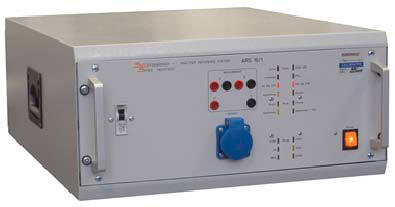
The Analyser
Reference System type ARS contains the core of the well known and reliable
analyzer (Ducati/Boconsult B10) for the measurement part, the standard
impedance according to IEC/EN 60725 as well as a phase- and current range
switching.
It allows harmonics measurements according to IEC/EN 61000-3-2
and flicker measurement
All the required diagram connections for the two types of measurement are performed automatically by ARS without any manual operation: this increases the reliability of the measurement avoiding any possible wiring error of the operator and ensures fast and reasonable operation with the test system.
|
Special Features: Simultaneous two-channel measurement for source check (flicker measurement) Calibratable Line Impedance Simulating Network meets IEC/EN 60725 (2012-06) Digital flickermeter meets IEC/EN 61000-4-15 (2010-08) Ed. 2.0 Real-time Harmonic Analyser meets IEC/EN 61000-4-7 (2009-10) Ed. 2.1 The Relating Standards:
IEC/EN
61000-3-2 |
Eurofins York Harmonics & Flicker Generator |
|||||||
|
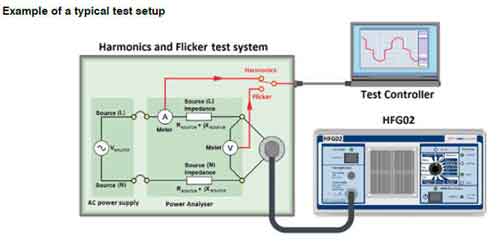
HFG02 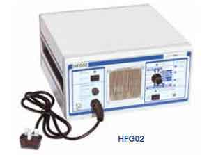 EN61000-3-2 2014
EN61000-3-3
2014
|
The Harmonics & Flicker Generator (HFG02) is a multifunction electronic load for the purpose of verifying harmonic and flicker test equipment. It provides an easy and reliable way to externally check the performance of the measurement system to the EN/IEC 61000-3-2 harmonics and interharmonics and EN/IEC 61000-3-3 flicker standards. A reference source is particularly useful where there is little intuitive sense of the expected response and the tests rely on software control and calculation to produce a result. |
||||||
|
|
|||||||
|
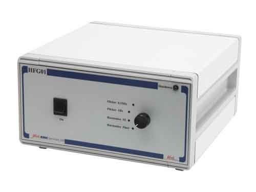
HFG01
EN61000-3-2 2014 EN61000-3-3 2014
|
The Harmonics & Flicker Generator (HFG01) has been
designed by York EMC Services Ltd for the purpose of verifying harmonic
and flicker test equipment. Until now there has been no easy and
reliable way to externally check the performance of the measurement
system to the EN/IEC 61000-3-2 harmonics and EN/IEC 61000-3-3 flicker
standards.
The HFG01 allows the user to periodically verify their test equipment, ensuring compliance with standards and laboratory quality procedures. The unit provides a series of harmonic and flicker disturbances of a nominal but stable level. The generator may therefore be used to verify the stability of a measurement system. Alternatively due to its stability it may be used as a transfer standard from a calibrated system.
|
||||||
|
Applications
|
Operation
The unit is a standalone device and requires no additional equipment. A four-way rotary switch selects the mode of operation. The modes are defined by firmware running on a micro-controller. This will enable the characteristics of the generator to be reprogrammed in line with future changes to the standards. The HFG01 simulates equipment under test (EUT), generating known, repeatable levels of harmonic and flicker disturbance in one of four modes of operation. In Steady State harmonics (SS) mode, a harmonic-rich current waveform is generated, allowing the harmonic measurement system to be verified. In this mode the generator simulates Class D equipment and produces harmonic levels that will fail the EN/IEC61000-3-2 pre A14 and A14 Class D limits. This mode will pass EN/IEC61000-3-2 pre A14 and A14 Class A limits. Fluctuating harmonics (FL) mode alternates between two distinct current waveforms over a 10-second cycle. This mode again fails the EN/IEC61000-3-2 pre A14 Class D limits but passes the A14 limits. In flicker test mode, a fixed level of mains disturbance is generated at a rate of 8.33Hz or 1Hz.
|
||||||
Laplace Harmonics & Flicker Analyzer |
|||||||||||||||||||||||||||||||||||||||||||||||||||||||||||||||||||||||||||||||
|
LAPLACE INSTRUMENTS
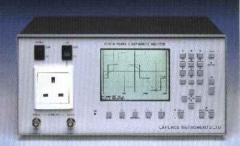
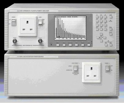
AC2000A
EN61000-3-2 : 2014 EN61000-3-3 : 2014 EN60868
|
The AC2000A is a fast, easy to use mains and harmonics analyzer with full graphical display. It is capable of continuous real-time analysis of both voltage and current. As a general purpose mains analyzer it can measure Watts, VA Vrms, Vpk, Arms, Apk, Crest factors, THD, Power factor, Frequency and Inrush current.As a harmonics analyzer it is a quick and convenient instrument for pre-compliance measurements using normal mains supply and is capable of full compliance measurements to EN61000-3-2 in conjunction with a suitable power source.As an option, the AC2000 can be operated as a conformance quality flicker meter in conformance with EN60868 and EN61000-3-3. | ||||||||||||||||||||||||||||||||||||||||||||||||||||||||||||||||||||||||||||||
|
|||||||||||||||||||||||||||||||||||||||||||||||||||||||||||||||||||||||||||||||
Laplace Low Distortion Power Supply |
|||||||||||||||||||||||||||||||||||
|
LAPLACE
INSTRUMENTS
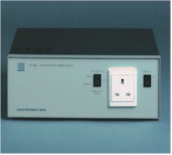
AC1000A
IEC61000-3-2 : 2014
|
Provides a source compliant with EN61000-3-2 : 2014 Up to 4.4A rms load current l000W at 230V Up to 10 A peak Overload protection
The AC1000A is an
innovative, low cost, pure power source designed specifically for use with a
harmonics analyzer such as the Laplace AC2000A, permitting compliance
quality measurements to EN61000-3-2.
|
||||||||||||||||||||||||||||||||||
|
|||||||||||||||||||||||||||||||||||
|
Copyright © 2001- R. A. Mayes Company, Inc. An Electro Mechanical Research and Development (EMRAD) Corporation, Company See our Privacy Policy All the data files on our website require Adobe Acrobat Reader! |