|
|
|
|
|
|
|

|
|
|
|
|
|
|
|
|
| Current & Injection Probes |
|
|
|
|
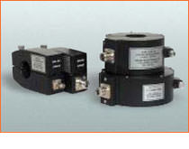
CURRENT PROBESCurrent probes required by various EMI specifications (such as MIL-STD-461/2) are toroidal transformers designed to measure RF currents on active power lines or other conductors. APPLICATION
A current probe is used as a "pick-up" device for
measuring RF current in single conductors or cable bundles when
connected to the 50 ohm input DESCRIPTION Direct connection to the conductor carrying EMI current is not necessary, since the probe may be opened for insertion of the conductor into the window of the toroid and then closed again to form a toroidal transformer with the conductor acting as a one-turn primary. A correction factor graph is provided to convert measured microvolts to EMI microamperes. When the EMI current is measured in dB above one microvolt as indicated on a conventional EMI meter, the correction factor will convert the measurement to dB above one microampere. The correction factor is the inverse of the transfer impedance, Zt. Each probe is shipped with a graph of the correction factor versus frequency, keyed to the serial number on the probe. Under certain conditions, a current probe can be used to inject low level RF signals into individual wires or cable bundles. |
INJECTION PROBESSpecifications require the injection of large high frequency currents into cable bundles and individual wires, using inserted secondary toroidal transformers placed around the conductors being tested. APPLICATION High power RF amplifiers with 50 ohm output impedance are used to deliver voltage to the injection probe. The wire or cable through the window of the probe acts as a secondary of the toroidal transformers. This test method is intended to be used instead of earlier methods, such as CS-01, CS-02, and RS-02 of MIL-STD-461. DESCRIPTION Bulk Current Injection Probes are available in two styles: 1. Fixed window style where the wire(s) under test must be passed through the window. 2. A split toroidal design where the probe can be opened up and clamped over the wire(s) under test.
Each probe is calibrated for insertion loss and transfer impedance in a test fixture designed for the particular window size. This fixture provides a signal path with a low Voltage Standing Wave Ratio. A typical fixture is Solar Type 9125-1, used for probes with 32 to 44 mm diameter windows. Ask for details on this and other test fixtures.
|
|
|
|
EMI Current Injection Probes |
 |
 |
CLAMP-ON INJECTION PROBES |
||||||||
|---|---|---|---|---|---|---|---|---|
|
SOLAR TYPE NO. |
WINDOW DIAMETER |
WINDING CURRENT |
RATED WATTS |
INSERTION LOSS |
FREQUENCY RANGE |
|||
|
UNDER 6 dB |
UNDER 10 dB |
UNDER 15 dB |
UNDER 20 dB |
|||||
|
9108-1N |
1.25" (32 mm) |
10 |
50 |
|
|
120 KHz - 70 MHz |
60 KHz - 150 MHz |
10 KHz - 200 MHz |
|
9120-1N |
1.25" (32 mm) |
30 |
50 |
|
12 MHz - 600 MHz |
7 MHz - 900 MHz |
4 MHz - 1GHz |
4 MHz - 1 GHz |
|
9121-1N |
1.25" (32 mm) |
30 |
50 |
|
100 MHz - 550 MHz |
50 MHz - 800 MHz |
30 MHz - 1GHz |
10 MHz - 1 GHz |
|
1.50" (38 mm) |
50 |
200 |
10 MHz - 350 MHz |
5 MHz - 430 MHz |
2.5 MHz - 500 MHz |
1.5 MHz - 500 MHz |
2 MHz - 500 MHz |
|
|
1.50" (38 mm) |
26 |
100 |
|
200 KHz - 8 MHz |
70 KHz - 90 MHz |
40 KHz - 100 MHz |
10 KHz - 100 MHz |
|
|
9217-1N |
1.50" (38 mm) |
26 |
100 |
800 KHz - 1.5 MHz |
500 KHz - 40 MHz |
250 KHz - 100 MHz |
150 KHz - 100 MHz |
10 KHz - 100 MHz |
|
9310-1N |
2.62" (67 mm) |
26 |
100 |
|
15 MHz - 450 MHz |
800 MHz - 650 MHz |
4 MHz - 800 MHz |
5 MHz - 800 MHz |
|
9607-1N |
1.25" (32 mm) |
10 |
50 |
|
500 KHz - 1 MHz |
200 KHz - 30 MHz |
120 KHz - 300 MHz |
10 KHz - 300 MHz |
|
Injection probes can also be used as current probes. A correction factor graph and instructions for its use are supplied. |
||||||||
PROBE CALIBRATION FIXTURES |
|
|---|---|
|
Note: Except for p/n 9125-1 and 9357-1 The probes are supported and centered in the fixture |
|
|
Model |
Description |
|
9125-1 |
For Injection Probes, 1.5" (32 mm - 44 mm) diameter window. 20 Hz to 500 MHz. Type BNC connectors. |
|
9125-2 |
For Solar 9119-1N Probe and similar, 1.25" (32 mm) diameter window. 400 MHz to 3 GHz. Type N connectors. |
|
9251-1 |
For Eaton, Stoddart and Solar Probes, 1.25" (32 mm) diameter window. 20 Hz to 500 MHz. Type BNC connectors. |
|
9254-1 |
For Eaton, Stoddart and Solar Probes, 2.62" (66 mm) diameter window. 20 Hz to 500 MHz. Type N connectors. |
|
9321-1 |
For Eaton, Stoddart and Solar Probes, 0.75" (19 mm) diameter window, totally enclosed. 20 Hz to 1.5 GHz. Type BNC connectors. |
|
9330-1N |
For Eaton, Stoddart and Solar Probes, 1.25" (32 mm) diameter window, totally enclosed. 20 Hz = 1.0 GHz. Type N connectors. |
|
9357-1 |
Clam Shell Fixture for Solar 9335-2 Probe. 20 Hz to 100 MHz. Type BNC connectors. |
|
Copyright © 2001- R. A. Mayes Company, Inc. An Electro Mechanical Research and Development (EMRAD) Corporation, Company See our Privacy Policy All the data files on our website require Adobe Acrobat Reader! |