|
|
|
|
|
|
|

|
|
|
|
|
|
|
|
|
| Tech Notes |
|
|
Tech Notes, Articles & Information |
|
Shielding Effectiveness Attenuation Information(typical products we sell - these are maximum values with optional components) |
|||||
|
Model |
Magnetic 15KHz |
Electric/Plane Waves |
Microwave 10GHz |
||
| 15KHz | 400MHz | 1GHz | |||
|
USC - 26 |
58dB |
120dB |
120dB | 120dB |
110dB |
|
USC - 44 |
40dB |
100dB |
100dB | 85dB |
60dB |
|
AL2.5 |
15dB |
65dB |
45dB | 40dB |
40dB |
|
AL5 |
40dB |
90dB |
92dB | 90dB |
88dB |
|
AL20 |
50dB |
90dB |
100dB | 92dB |
90dB |
|
X25 |
40dB |
90dB |
92dB | 92dB |
90dB |
|
Ramsey AL |
- |
100dB |
100dB | 100dB |
60dB |
|
Ramsey SS |
- |
110dB |
110dB | 110dB |
98dB |
|
SFI DW Nova |
39dB |
35dB |
94dB | 98dB |
100dB |
|
SFI DW Juno |
36dB |
28dB |
70dB | 80dB |
80dB |
RF Shielding Effectiveness (dB) vs Attenuation Ratio vs Percentage Attenuation |
||
|
Shielding Effectiveness (dB) |
Attenuation Ratio |
Percent Attenuation |
|
20 |
10 : 1 |
90.0 |
|
40 |
100 : 1 |
99.0 |
|
60 |
1,000 : 1 |
99.9 |
|
80 |
10,000 : 1 |
99.99 |
|
100 |
100,000 : 1 |
99.999 |
|
120 |
1,000,000 : 1 |
99.9999 |
Shielding effectiveness values are expressed in logarithmic, not linear, terms. Therefore, 80 dB of shielding effectiveness is not double the 40 dB level, but 100 times greater. Another way to express effectiveness is attenuation ratio, which compares the attenuation signal strength outside and inside the shield as shown above.
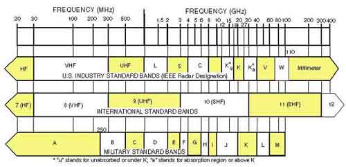
Radio Frequency Allocation Chart |
|||||||||||||||||||||||||||||||||||||||||
|
|
|||||||||||||||||||||||||||||||||||||||||
|
|
|||||||||||||||||||||||||||||||||||||||||
Anechoic Chamber Absorber Tech Notes |
|||||||||||||||||||||||||||||||||||||||||
5G NR Frequency Bands Information |
|||||||||||||||||||||||||||||||||||||||||
EMC Antenna Tech Notes |
|||||||||||||||||||||||||||||||||||||||||
|
Antenna Impedance |
|||||||||||||||||||||||||||||||||||||||||
Mismatch Effects
In addition to matching the impedance, most transmission sources have coaxial outputs. This type of connector has a grounded shield surrounding the center conductor, which carries the RF/Microwave energy. Many antennas are balanced and both sides of the transmission line are active (such as 300 W twin lead for radio and television). This requires that not only the impedance be transformed but that the unbalanced coax transmission line is transformed into a balanced condition prior to connection to the antenna. The device that accomplishes this is generally referred to as a balun. It is important to note that the best match is obtained with a dummy load, which does not generally radiate at all. This leads to the next topic, efficiency |
|||||||||||||||||||||||||||||||||||||||||
|
Gain
Gain is a widely used parameter directly measurable by substituting an
antenna with known gain (generally a gain reference antenna) in for an
antenna under test (AUT). The output levels of the AUT and the gain
reference can then be measured for the same incident field. The gain can
then be determined by comparing those measured levels. Gain of an
antenna is expressed in dB, 10log10(numerical gain), which is generally
referenced to an isotropic radiator (radiates equally in all directions)
and expressed as dBi. Typical gains are listed in table 2. The gain
expressed for an antenna is generally the maximum or peak gain. This
leads to the second part of the gain equation, directivity. Several examples of typical antenna gains and HPBW are listed in table B, typical antenna gains and beam-widths. |
|||||||||||||||||||||||||||||||||||||||||
|
Antenna Efficiency Information Antenna efficiency is a complicated and often misused figure. All antennas suffer from losses. A simple horn antenna for example will not be as efficient as a perfect aperture of the same size because of phase offset. The real efficiency of an antenna combines impedance match with other factors such as aperture and radiation efficiency to give the overall radiated signal for a given input. The best and most widely used expression of this efficiency is to combine overall efficiency with directivity (of the antenna) and express the efficiency times directivity as gain. Table B, Typical Antenna Gains and Beam-widths
|
|||||||||||||||||||||||||||||||||||||||||
|
Directivity
|
|||||||||||||||||||||||||||||||||||||||||
|
Polarization |
|||||||||||||||||||||||||||||||||||||||||
EMC / RFI Filters Information |
|||||||||||||||||||||||||||||||||||||||||
EMI / RFI Receiver Articles |
|||||||||||||||||||||||||||||||||||||||||
|
Standard Connection Speeds Information |
|||
| Devices, Interfaces, Protocols, Standards |
Data Rate (Bits / Sec) |
Date |
Description |
| TAT-1 | 51-calls | 1956 | The first transatlantic coaxial telephone cable, 7,802km Out-of-service retired 1978 |
| Bell 103 | 300bps | 1965 | Asynchronous data transmission, full-duplex, 2-wire dialup or leased line. |
| CCITT V.21 | 300bps | 1965 | The standard for full-duplex communication at 300 baud in Japan and Europe. |
| Dataphone | 300bps | 1958 | 1st Modem: Bell Labs, Hayes AT commands. |
| Bell 212a | 1.2K | 1988 | Synchronous - asynchronous data transmission, full-duplex operation, 2-wires. |
| ITU V.22 | 1.2K | 1988 | Standard protocol for transmitting data on telephone lines |
| Cat1 | 1.2K | 1985 | Basic telephone wire, Voice Only |
| Category 1 | 1.2K | 1985 | Basic telephone wire, Voice Only |
| 1,200 baud | 1.2K | 1962 | 2nd Modem speed. Basic telephone line transmission rate |
| POTS | 1.2K | 1877 | Plain Old Telephone Service, the first commercial telephones |
| ITU V.22bis | 2.4K | 1988 | Standard protocol for transmitting data with telephone lines. |
| 2,400 baud | 2.4K | 1980 | 3rd Modem speed |
| ITU V.29 | 9.6K | 1988 | Standard protocol for transmitting data with telephone lines |
| ITU V.32 | 9.6K | 1991 | Standard protocol for transmitting data with telephone lines |
| Facsimile | 9.6K | 1980 | FAX Machines / FAX Modems |
| 9,600 baud | 9.6K | 1984 | 4th Modem speed |
| ITU V.32bis | 14.4K | 1991 | Standard protocol for transmitting data with telephone lines |
| 14,400 baud | 14.4K | 1991 | V.32bis Modem, V.17 fax |
| UART 8250 | 19.2K | 1981 | Universal Asynchronous Receiver-Transmitter, 0-byte buffer. |
| RS-232 | 20.0K | 1987 | 50ft, Serial Port, single-ended data transmission |
| RS-366 | 20.0K | 1988 | Uses RS-232 electrical specs, different connector pin outs and signal functions. |
| 28,800 baud | 28.8K | 1994 | V.34, Rockwell V. Fast Modems |
| GeoPort | 28.8K | 1996 | A serial port for Apples that provides interface between telephone and computer |
| 33,600 baud | 33.6K | 1996 | Maximum data transmission rate with copper telephone wires. |
| ITU V.34 (V.fast) | 36.6K | 1998 | Standard protocol for transmitting data with telephone lines |
| UART 16450 | 38.4K | 1995 | Universal Asynchronous Receiver-Transmitter, 1-byte buffer. |
| K56flex | 48.0K | 1998 | V.90, Proprietary protocol By: Lucent Technologies |
| X2 | 48.0K | 1998 | V.90, Proprietary protocol By: US Robotics |
| Modem, Analog | 48.0K | 1958 | MOdulator - DEModulator, sends at 33.6K, receives at 48K |
| ITU V.90 | 56.0K | 1998 | Standard protocol for transmitting data with telephone lines |
| Modem, Digital | 56.0K | 1990 | MOdulator - DEModulator, sends at 56K, receives at 56K |
| HSCSD | 57.6K | 1999 | High Speed Circuit Switched Data, (wireless) |
| DS-0 | 64.0K | 1962 | Digital Signal Level 0, 1 Channel (1/24 of T1) |
| E-0 | 64.0K | 1 Channel, Europe & Japan | |
| J-0 | 64.0K | 1 Channel, Japanese | |
| N-ISDN | 64.0K | 1976 | Narrowband Integrated Services Digital Network |
| RS-423 | 100.0K | 1995 | 4000ft, Single-ended data transmission |
| GPRS | 114.0K | 1999 | General Packet Radio Service, RF in space (wireless) |
| Modem, Null | 115.2K | 1987 | Special cable allowing two computers to communicate with RS-232 ports. |
| PS/2 | 115.2K | 1987 | By IBM for keyboards and pointing devices. |
| RS-232e | 115.2K | 1987 | 50ft, Serial Port, single-ended data transmission |
| UART 16550 | 115.2K | 1995 | Universal Asynchronous Receiver-Transmitter, 16-byte buffer. |
| ISDN-BRI | 128.0K | 1980 | BRI (Basic Rate Interface) 2x64K B-channels, 1x64K D-channel |
| Euro-ISDN | 144.0K | 1993 | 128K usable. Allows full transparent inter-working between all European countries |
| Parallel Port | 150.0K | 1981 | IBM's first printer port. |
| LocalTalk | 230.0K | 1983 | 300m Apple Computer's AppleTalk networking scheme. |
| MAX3100 | 230.0K | 1997 | Multi-drop communication technique known as 9-bit mode. the world's smallest UART |
| EDGE | 384.0K | 2000 | Enhanced Data GSM Environment. Global System for Mobile (GSM) wireless service. |
| Satellite Dish | 400.0K | 1957 | RF in space, wireless WAN, sends at 33.6K, receives at 400K |
| UART 16650 | 460.8K | 1995 | Universal Asynchronous Receiver-Transmitter, 32-byte buffer. |
| UART 16750 | 921.6K | 1995 | Universal Asynchronous Receiver-Transmitter, 64-byte buffer. |
| 1Base5 | 1.000M | 1986 | 250 Meters Two pairs of twisted telephone cable. |
| StarLAN | 1.000M | 1970 | 250 Meters Two pairs of twisted telephone cable. |
| B-ISDN | 1.500M | 1988 | Broadband Integrated Services Digital Network |
| G.lite | 1.500M | 1998 | 18000 feet Asymmetric Digital Subscriber Line, sends at 512K, receives at 1.5M |
| IDSL | 1.500M | 1997 | 18000 ft, DSL over ISDN, sends 64K-1.5M, receives 1.5-9M |
| Modem, Cable | 1.500M | 1997 | Sends at 3M, receives at 1.5M. |
| DS-1 | 1.544M | 1975 | Digital Signal Level 1, 24 Channels (1xT1) |
| HDSL | 1.544M | 1991 | 12000 ft, High bit-rate DSL, sends at 2.048M, receives at 1.544M |
| SDSL | 1.544M | 1998 | 12000 ft, Symmetric DSL, sends at 2.048M, receives at 1.544M |
| T-1 | 1.544M | 1957 | Trunk Level 1, 24 Channels (1xT1) Time-Division Multiplexing By: AT&T |
| ISDN-PRI | 1.544M | 1988 | Primary Rate Interface 23x64K B-channels, 1x64K D-channel on T1, 23B+D |
| J-1 | 1.544M | 24 Channels, Japanese | |
| RS-449 | 2.000M | 1970 | 1km, Serial binary data interchange |
| Twinax | 2.000M | 1980 | 4000 ft, Unike coax has 2 conductors in center. |
| E-1 | 2.048M | 1997 | 30 Channels, Europe & Japan, 1.920M usable |
| Euro ISDN-PRI | 2.048M | Primary Rate Interface 30x64K B-channels, 1x64K D-channel on E1, 30B+D | |
| ARCnet | 2.500M | 1968 | Attached Resource Computer Network By: Datapoint. |
| OX16C952 | 3.000M | 1992 | The newest and fastest PC UART, the deepest FIFOs 128-byte buffer. |
| DS-1c | 3.152M | 1985 | Digital Signal Level 1c, 48 Channels (2xT1) |
| J-1c | 3.152M | 48 Channels, Japanese | |
| T-1c | 3.152M | 1985 | Trunk Level 1c, 48 Channels (2xT1) Time-Division Multiplexing |
| UMTS | 3.500M | 1998 | Universal Mobile Telephone System or often referred to as 3G |
| Cat2 | 4.000M | 1990 | 1Mhz Used for Apple computer's LocalTalk |
| Category 2 | 4.000M | 1990 | 1Mhz Used for Apple computer's LocalTalk |
| IrDA | 4.000M | 1994 | Infrared Data Association, wireless communication standard |
| DS-2 | 6.312M | 1969 | Digital Signal Level 2, 96 Channels (4xT1) |
| J-2 | 6.312M | 96 Channels, Japanese | |
| T-2 | 6.312M | Trunk Level 2, 96 Channels (4xT1) Time-Division Multiplexing | |
| ADSL | 8.000M | 1997 | Asymmetric DSL, sends at 1.500M, receives at 8.000M |
| E-2 | 8.448M | 120 Channels, Europe & Japan | |
| 10Base-T | 10.000M | 1995 | 100 meters, Ethernet (Unshielded Twisted Pair) Cat3 |
| 10Base-2 | 10.000M | 1985 | 185 meters, (Cheapernet) Thin Net Ethernet 50 ohms Thin Coaxial |
| 10Base-5 | 10.000M | 1985 | 500 meters, Thick Net Ethernet 50 ohms (Thick Coaxial) |
| 10Base-F | 10.000M | 1993 | 2000 meters, (fiber-optic) |
| 10Broad36 | 10.000M | 1985 | 3600 meters, Ethernet specification using broadband coaxial (CATV) cable. |
| Cat3 | 10.000M | 1991 | 16MHz Voice Grade twisted-pair wire. |
| Category 3 | 10.000M | 1991 | 16MHz Voice Grade twisted-pair wire. |
| CAIS bus | 10.000M | 1991 | Common Airborne Instrumentation System, a transformer coupled comm. link. |
| DECnet PhaseIV | 10.000M | 1983 | First released by Digital in 1983 for its VMS and RSX-11 systems. |
| RS-422a | 10.000M | 4000ft, Differential Data Transmission | |
| RS-485 | 10.000M | 4000ft, Balanced line interface, 2-wire, half-duplex, differential. | |
| RS-530 | 10.000M | 30km, fiber-optic Point to Point | |
| Standard SCSI | 10.000M | 1995 | SCSI-1,Small Computer System Interface |
| Wireless LAN | 11.000M | 1997 | Ethernet performance for use within premises and zones. 802.11 technologies |
| USB 1.1 | 12.000M | 1996 | 5 meters, Universal Serial Bus, external bus standard |
| Token Ring | 16.000M | 1982 | LAN, a type of computer network |
| EIDE | 16.600M | 1993 | Enhanced Integrated Drive Electronics |
| ARCnet Plus | 20.000M | 1992 | Attached Resource Computer Network |
| Cat4 | 20.000M | 1990 | 20MHz Twisted-pair wire, Token Ring |
| Category 4 | 20.000M | 1990 | 20MHz Twisted-pair wire, Token Ring |
| Fast Wide SCSI | 20.000M | 1986 | 1.5m, Small Computer System Interface |
| MCA | 20.000M | 1987 | Micro Channel Architecture |
| ECP/EPP | 24.000M | 1994 | High performance bi-directional parallel port. |
| ATM-25 | 25.600M | 1991 | Asynchronous Transfer Mode, uses fixed length packets called cells. |
| ZV-Port | 27.000M | 1996 | Zoomed Video via PCMCIA bus to VGA controller. |
| J-3 | 32.064M | 480 Channels, Japanese | |
| EISA | 33.000M | 1982 | Extended Industry Standard Architecture |
| E-3 | 34.368M | 480 Channels, Europe & Japan | |
| Ultra SCSI | 40.000M | 1993 | SCSI-3, Small Computer System Interface |
| VMEbus | 40.000M | 1980 | Industrial controls: factory automation, robotics, etc. |
| VSAT | 40.000M | 1958 | Very Small Aperture Terminal Satellite Communication, antenna of 1.8 meter dia. |
| DS-3 | 44.736M | 1972 | Digital Signal Level 3, 672 Channels (28xT1) |
| T-3 | 44.736M | 1991 | Trunk Level 3, 672 Channels (28xT1) Time-Division Multiplexing |
| V-ADSL | 51.000M | 1995 | 51.00M at 1000 feet & 25.600Mbps at 3000-4000 feet |
| STS-1c | 51.840M | 1986 | Synchronous Transport Signal, Level 1 |
| OC-1c | 51.840M | Optical Carrier Level 1, fiber-optic, 672 Voice Circuits | |
| VDSL | 52.000M | 1995 | Very high speed DSL, send 1.5-2.3M, receive 13-52M |
| HSSI | 53.000M | 1989 | 50 ft, High-Speed Serial Interface |
| DS-3c | 89.472M | Digital Signal Level 3c, 1344 Channels (56xT1) | |
| T-3c | 89.472M | Trunk Level 3c, 1344 Channels (56xT1) Time-Division Multiplexing | |
| J-4 | 97.200M | 5760 Channels, Japanese | |
| J-3c | 97.728M | 1440 Channels, Japanese | |
| 100Base-F | 100.000M | 1984 | Fast Ethernet with fiber-optic Cable. |
| 100Base-T | 100.000M | 1993 | 100 meters, Fast Ethernet (Unshielded Twisted Pair) Cat5 |
| 100Base-T2 | 100.000M | 1991 | Fast Ethernet (2-pairs of normal-quality twisted-pair wire) Cat3 |
| 100Base-T4 | 100.000M | 1991 | 100 meters Fast Ethernet (4-pairs of normal-quality twisted-pair wire) Cat3 |
| 100Base-TX | 100.000M | 1993 | 220 meters, Fast Ethernet (Unshielded Twisted Pair) Cat5 |
| 100VG-AnyLAN | 100.000M | 1997 | 200 meters, Voice Grade Cat3+ on Any LAN |
| Cat5 | 100.000M | 1993 | 100MHz, Unshielded twisted-pair wire, Fast Ethernet |
| Category 5 | 100.000M | 1993 | 100MHz, Unshielded 4 twisted-pair wire, Fast Ethernet, RJ-45 connector. |
| CDDI | 100.000M | 1993 | Copper Data Distribution Interface, the copper version of FDDI |
| FDDI | 100.000M | 1993 | Fiber Distributed Data Interface, uses a token ring protocol. |
| Cat7 | 100.000M | 1997 | 600Mhz, Unshielded twisted-pair wire (standard pending) |
| Category 7 | 100.000M | 1997 | 600Mhz, Unshielded twisted-pair wire (standard pending) |
| FibreChannel | 125.000M | 1988 | fiber-optic-based, computer peripheral architecture. |
| DS-3d | 135.000M | Digital Signal Level 3d, (87xT1) By: AT&T | |
| T-3d | 135.000M | Trunk Level 3d, (87xT1) Time-Division Multiplexing | |
| E-4 | 139.264M | 1920 Channels, Europe & Japan | |
| ESCON | 150.000M | 1996 | Enterprise Systems Connection - A star topology invented |
| STM-1 | 155.520M | Synchronous Transport Module, Level 1 | |
| STS-3c | 155.520M | 1986 | Synchronous Transport Signal, Level 3 |
| OC-3c | 155.520M | Optical Carrier Level 3, fiber-optic, 2016 Voice Circuits | |
| AGP 2.0 | 266.000M | 1998 | Accelerated Graphics Port |
| DS-4 | 274.176M | 1976 | Digital Signal Level 4, 4032 Channels (168xT1) |
| T-4 | 274.176M | Trunk Level 4, 4032 Channels (168xT1) Time-Division Multiplexing | |
| FireWire | 400.000M | 1995 | A serial SCSI variant developed by Apple |
| STM-3 | 466.560M | Synchronous Transport Module, Level 3 | |
| STS-9c | 466.560M | 1986 | Synchronous Transport Signal, Level 9 |
| OC-9c | 466.560M | Optical Carrier Level 9, fiber-optic, 6048 Voice Circuits | |
| USB 2.0 | 480.000M | 1999 | Universal Serial Bus, external bus standard v2.0 |
| PCI 2.2 | 533.000M | 1993 | Peripheral Component Interconnect |
| TPC-4 | 560.000M | 1992 | Trans-Pacific Cable 4, Vancouver Island & Manchester, CA on the Pacific Ocean. |
| TAT-8 | 565.000M | 1988 | fiber-optic cable network laid from Tuckerton NJ to England and France. |
| TAT-9 | 565.000M | 1991 | fiber-optic cable network laid from North America to Europe. |
| TAT-10 | 565.000M | 1992 | fiber-optic cable network, links United States with Germany and The Netherlands. |
| TAT-11 | 565.000M | 1993 | France Telecom, fiber-optic cable network from Manahawkin to England and France. |
| TAT-12 | 565.000M | 1996 | 1st fiber-optic cable network to operate as a fully backed-up "self-healing" cable loop. |
| TAT-13 | 565.000M | 1996 | 2nd fiber-optic cable network to operate as a fully backed-up "self-healing" cable loop. |
| E-5 | 565.148M | 7680 Channels, Europe & Japan | |
| ATM | 622.000M | 1988 | Asynchronous Transfer Mode |
| STM-4 | 622.080M | Synchronous Transport Module, Level 4 | |
| STS-12c | 622.080M | 1986 | Synchronous Transport Signal, Level 12 |
| OC-12c | 622.080M | 15000 meters Optical Carrier Level 12, fiber-optic, 8064 Voice Circuits | |
| OC-18c | 933.120M | Optical Carrier Level 18, fiber-optic, 12096 Voice Circuits | |
| 1000Base-CX | 1.000G | 1998 | 25 meters 2-pair 150 ohms STP, Gigabit Ethernet, copper cable. |
| 1000Base-F | 1.000G | 1996 | Gigabit Ethernet with fiber-optic Cable. |
| 1000Base-LX | 1.000G | 1998 | 550 meters Gigabit Ethernet, long wavelength laser transmitters, fiber-optic cable. |
| 1000Base-SX | 1.000G | 1998 | 5000 meters Gigabit Ethernet, short wavelength laser transmitters with fiber-optic cable. |
| 1000Base-T | 1.000G | 1999 | 100 meters Gigabit Ethernet, four pairs of 100-ohm Cat5 or better cable |
| 1000Base-X | 1.000G | 1998 | Gigabit Ethernet, with twisted pair cable. |
| Ethernet | 1.000G | 1976 | 10M to 1000M |
| PCI-X | 1.000G | 1999 | 133 MHz Industry-standard I/O interconnect |
| WidebandATM | 1.000G | 1996 | Gigabit Ethernet with fiber-optic cable. |
| PC150 SDRAM | 1.200G | 2000 | PC150 Synchronous DRAM |
| OC-24c | 1.244G | Optical Carrier Level 24, fiber-optic, 16128 Voice Circuits | |
| DRDRAM | 1.600G | 1999 | Direct Rambus Dynamic Random Access Memory |
| HIPPI-PH | 1.600G | 1987 | High-Performance Parallel Interface physical layer |
| RDRAM | 1.600G | 1999 | Rambus Dynamic Random Access Memory |
| SLDRAM | 1.600G | 1997 | Synchronous Link Dynamic Random Access Memory |
| QuickRing | 1.700G | 1992 | A high speed point-to-point data transfer architecture from Apple |
| OC-36c | 1.866G | Optical Carrier Level 36, fiber-optic, 24192 Voice Circuits | |
| SDRAM | 2.100G | 1996 | Synchronous Dynamic Random Access Memory |
| SciNet | 2.325G | 1995 | fiber-optic, part of the vBNS backbone |
| Cat6 | 2.400G | 1999 | 250MHz, Cable standards under development |
| Category 6 | 2.400G | 1999 | 250MHz, Cable standards under development |
| SONET | 2.488G | 1988 | Synchronous Optical NETwork-Designed by the telcos. |
| STM-16 | 2,488G | 1997 | Synchronous Transport Module, Level 16 |
| STS-48c | 2,488G | 1986 | Synchronous Transport Signal, Level 48 |
| OC-48c | 2.488G | 2000 | Optical Carrier Level 48, fiber-optic, 32256 Voice Circuits |
| SERDES | 2.500G | 1993 | SERializer/DESerializer ASIC transceiver core By: Texas Instruments |
| InfiniBand | 2.500G | 2000 | Next Generation I/O |
| vBNS | 2.500G | 1986 | Very high-speed Backbone Network Service |
| OC-96c | 4.976G | Optical Carrier Level 96, fiber-optic, 64512 Voice Circuits | |
| CANTAT-3 | 5.000G | 1994 | Cable to Nova Scotia via Iceland & Faroes, Northern England, Denmark & Germany. |
| FLAG | 5.300G | 1997 | Fiber-optic Link Around the Globe, 27,300km linking Great Britain and Japan. |
| OC-192c | 9.953G | 2000 | Optical Carrier Level 192, fiber-optic, 129024 Voice Circuits |
| LDT bus | 12.000G | 2001 | AMD's Lighting Data Transport bus. |
| RoX-II bus | 12.800G | 1998 | (Ring Of Switches) bus architecture |
| OC-256 | 13.271G | Optical Carrier Level 256, fiber-optic, 172032 Voice Circuits | |
| DDRSDRAM | 16.800G | 2000 | Double Data Rate Synchronous Dynamic Random Access Memory |
| OC-768 | 39.813G | 2002 | Optical Carrier Level 768, fiber-optic, 516096 Voice Circuits |
| OC-3072 | 159.252G | Optical Carrier Level 3072, fiber-optic, 2064384 Voice Circuits | |
| TAT-14 | 640.000G | 2000 | France Telecom, fiber-optic cable network spans 15,428 kilometers. |
| DWDM | 2.56T | 2002 | 2500 miles, 64-channel Dense Wave Division Multiplexing |
| Glass | 75.00 | ||
| Protocol | MB/s |
| IrDA-Control | 0.009 |
| Serial | |
| Parallel | |
| Bluetooth 1.1 | |
| Bluetooth 2 | |
| USB 1.1 | |
| USB 2.0 | |
| USB 3.0 | 640 |
| SCSI 1 | |
| Fast SCSI 2 | |
| Fast Wide SCSI 2 | |
| Ultra SCSI | |
| Ultra Wide SCSI | |
| Ultra2 SCSI | |
| Ultra 160 SCSI | |
| FireWire (IEEE 1394) | |
| FireWire (IEEE 1394b) |
|
Copyright © 2001- R. A. Mayes Company, Inc. An Electro Mechanical Research and Development (EMRAD) Corporation, Company See our Privacy Policy All the data files on our website require Adobe Acrobat Reader! |