AFJ Instruments EMI Receiver Systems
|
|

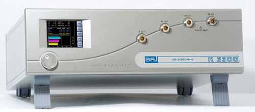
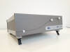
FFT 3100 & 3300 EMI Receivers
Radiated Emissions

|
Fully digital IF EMI Receivers for measurement of
radiated electromagnetic interference from 30MHz to 3GHz.
Compact
designed and manufactured compliant to CISPR 16 International Standard,
using FFT Scan Mode for fast measurements of radiated electromagnetic
interference in accordance with requirements of EMI International,
European and Product standards, pre-selectors and advanced software for
EMC testing.
|
|
Based on a PC integrated architecture with WINDOWS
10 Embedded OS, FFT 3100 & 3300 EMI Receivers are ready to operate with
advanced software for EMC testing, fitted with pre-selectors that allow
excellent dynamic range and precise conducted emission measurements
covering the frequency range from 30MHz tp 3GHz. Remote control with an
external PC is also possible.
- Compact unit designed and manufactured compliant
to CISPR 16-1-1.
- FFT Scan Mode compliant to CISPR 16-3.
- Peak, Quasi-Peak, CISPR Average, RMS and CISPR
RMS Detectors.
- Pre-selectors.
- Tracking Generator.
- Advanced software for EMC testing.
- Critical frequencies fast detection by through
overview measurement.
- 1Hz PRF CISPR 16-1-1 calibrated pulse weighting.
|
|
|
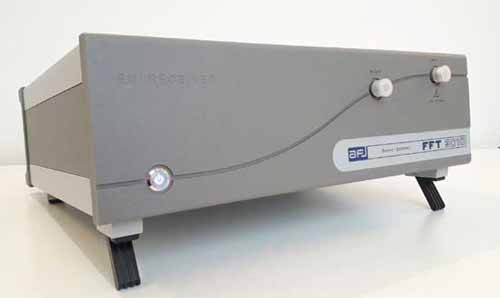
FFT 3010 & 3030 EMI Receivers
Conducted Emissions
|
Fully FFT digital EMI Receivers for measurement of
conducted electromagnetic interference from 9kHz to 300MHz.
Compact designed and manufactured compliant to CISPR 16 International
Standard, using FFT Scan Mode for fast measurements of conducted
electromagnetic interference in accordance with requirements of EMI
International, European and Product standards, pre-selectors and
advanced software for EMC testing.
|
|
Based on a PC integrated
architecture with WINDOWS 10 Embedded OS, FFT 3010 & 3030 EMI Receivers
are ready to operate with advanced software for EMC testing, fitted with
pre-selectors that allow excellent dynamic range and precise conducted
emission measurements covering the frequency range from 9kHz to 300MHz.
Remote control with an external PC is also possible.
- Compact unit designed and manufactured compliant
to CISPR 16-1-1.
- FFT Scan Mode compliant to CISPR 16-3.
- Peak, Quasi-Peak, CISPR Average, RMS and CISPR
RMS Detectors.
- Pre-selectors.
- Tracking Generator.
- Advanced software for EMC testing.
- 1Hz PRF CISPR 16-1-1 calibrated pulse weighting.
FFT 3030 EMI Receiver is ideal suited for measurement of
electromagnetic interference in accordance with the requirements of
CISPR 14-1 (household appliances industry) and CISPR 15 (lighting
equipment industry) standards.
Further to conducted emission
measurements from 9kHz to 30MHz with LISN, CISPR 14-1 standard
requires radiated power emission measurements from 30MHz to 300MHz
with absorbing clamp, CISPR-15 standard requires radiated emission
measurements from 30MHz to 300MHz with CDN method.
|
|
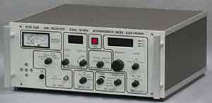
AFJ PAT20M Pulse Limiter
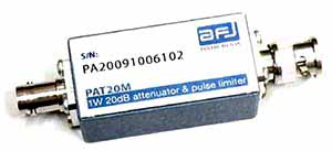
AFJ PAT20M Pulse Limiter
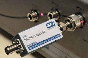
AFJ R3010 Receiver and PAT 20M
|
Why an attenuator and pulse limiter?
An Attenuator
and Pulse Limiter is used during EMI testing to provide input protection
to EMI receivers against high spikes coming from a LISN. |
The input attenuator, the preamplifier, the pre-selector or input mixer
can be destroyed in EUT testing due to a very high spectral
density/pulse energy. For high voltages as occur e.g. in LISNs or
absorbing clamp measurement, we strongly recommend to make use of the
external Pulse Limiter � Attenuator PAT 20M with every kind of EMI
Receiver.
This 20dB attenuator is designed for pulse voltages up
to 1Ws, to protect the input receivers. Even using EMI Test systems
already protected against spikes, for unknown devices under test, the
PAT 20M pulse limiter is strongly recommended. |
PAT 20M Specifications
• Frequency Range 0Hz-30MHz
• Low pass filter up to 100MHz
• Max continuous input power 1W
•
Max pulse input energy 1Ws (500 s)
• Input / Output VSWR 1.05 / 1.15
• Characteristic Impedance 50Ω
•
Insertion loss 20dB 0.3dB
• In / Out RF connectors BNC (female /
male)
• Dimensions 96mm x 28mm x 23mm
• Weight 70g
• Nominal
Temperature range -10°C to +45°C
• Storage temperature range -25°C to
+70°C |