|
|
|
|
|
|
|

|
|
|
|
|
|
|
|
|
| Magnetic Loop Antennas |

Schwarzbeck Magnetic Field Loop Antennas |
|
Active Magnetic Field Loop Antennas |
|
FMZB 1512
Frequency Range: 9 kHz - 30 MHz |
Schwarzbeck Active Receiving Loop Antenna |
FMZB 1513
Frequency Range: 9 kHz - 30 MHz |
Active Magnetic Loop Antenna acc. to CISPR 16 9 kHz to 30 MHz constant antenna factor 20 dB/m with built in NiMH-batteries detachable glass fiber handle 180 mm. Loop diameter: 50 cm Optimized for mobility Option: Opt. ACS 110: Charger ACS 110 for FMZB 1513 Opt. 500 mm Handle: Additional glass fiber handle of 500 mm length. CCA 1513 Transport case for FMZB 1513 and accessories. |
FMZB 1513-60
Frequency Range: 9 kHz - 30 MHz |
Active Magnetic Loop Antenna acc. to CISPR 16 9 kHz to 30 MHz constant antenna factor 20 dB/m with built in NiMH-batteries detachable glass fiber handle 180 mm. Loop diameter: 60 cm Optimized for mobility Option: Opt. ACS 110: Charger ACS 110 for FMZB 1513-60 Opt. 500 mm Handle: Additional glass fiber handle of 500 mm length. CCA 1513-60 Transport case for FMZB 1513-60 and accessories. |
FMZB 1519 B
Frequency Range: 9 kHz - 30 MHz |
Active Magnetic Loop Antenna acc. to CISPR 16 9 kHz to 30 MHz constant antenna factor 20 dB/m built in rechargeable battery Option: Opt. ACS 110: Charger ACS 110 for FMZB 1519 B |
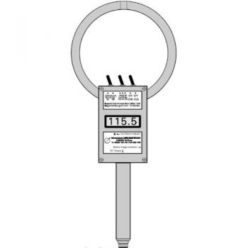
HMDA 1545
Frequency Range: 9 kHz - 50 (80) MHz |
Schwarzbeck Handheld Magnetic Field Meter LCD acoustic fieldstrength indication with tone generator 9 kHz - 50 (80) MHz 200µA/m - 1 A/m 6 x Type AA NiMH Option: ACS 410: ACS 410 charger for HMDA 1545 |
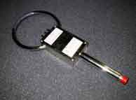
HFS 1546
Frequency Range: 150 kHz - 400 MHz |
Active Magnetic Field Probe with shielded 50-mm-Loop [Shorter version] available on request. |
FSH3D
Frequency Range: 9 kHz - 200 (300) MHz |
Isotropic H-Field Antenna for the Rohde und Schwarz handheld spectrum analyser FSH or the TS-EMF System. 9 kHz - 200 (300) MHz Light weight low attenuation radom Outer diameter ca. 150 mm The selection of the active loop and the power supply for the antenna is provided by the included short cable that can directly be connected to the R&S FSH. |
Passive Magnetic Antennas, RX-Loop |
|
|
|
|
HFRAE 5160 Frequency Range: 2 MHz - 300 MHz |
Receiving VHF - UHF loop antenna diam. 50 mm 2-300 MHz Transformer |
|
HFRAE 5161 
Frequency Range: 70 KHz - 120 MHz |
Schwarzbeck HF RX Loop diam. 100 mm 0.07 - 120 MHz 1 turn Transformer |
HFRAE 5162 Frequency Range: 50 KHz - 120 MHz |
VLF-HF RX Loop diam. 250 mm 0.05 - 30 MHz 1 turn Transformer |
HFRAE 5163
Frequency Range: 9 KHz - 300 MHz |
Passive magnetic loop antenna diam. 50 mm 0.009 - 300 MHz 1 turn Transformer |
HFRA 5164 Rx
Frequency Range: 10 KHz - 120 MHz |
Passive magnetic loop antenna diam. 100 mm 0.01 - 120 MHz 3 turns |
Passive Magnetic Antennas, TX-Loop |
|
|
|
|
|
|
|
HFRA 1356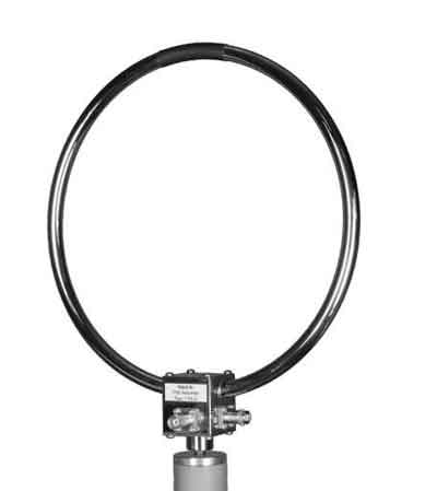
Frequency Range: 13.56 MHz (370 KHz BW) |
The HFRA 1356 is a passive loop antenna which is matched to a resonance frequency of 13.56 MHz with 370 kHz bandwidth (-3dB) The purpose of the antenna is to produce defined magnetic fields at 13.56 MHz efficiently, i.e. to test near field communication devices (NFC) or RFID equipment. NFC issues are described in the standards ISO 18092, ECMA 340, ETSI TS 102 190. diam. 250 mm 2 turns BNC - connectors 16 W |
HFRA SF02G Frequency Range: 11 KHz - 30 MHz |
Tuneable resonant magnetic loop antenna to generate extremely high magnetic fields in the range 10 kHz to 30 MHz acc. to VG95373-13:2008-11 and VG95373-23:2008-11. Including sensor loop HFRAE 5163 und control cable. |
HFRA 5148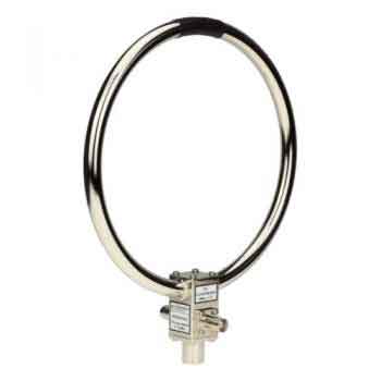 |
Circular Transmitting Loop Antenna diam. 180 mm 1 turn ISO 14708-3 |
|
HFRA 5149  Frequency Range: 9 KHz - 30 MHz |
Circular transmitting loop antenna 9 kHz - 30 MHz diam. 500 mm including 50 Ohm 20 Watt termination N-connectors |
HFRA 5152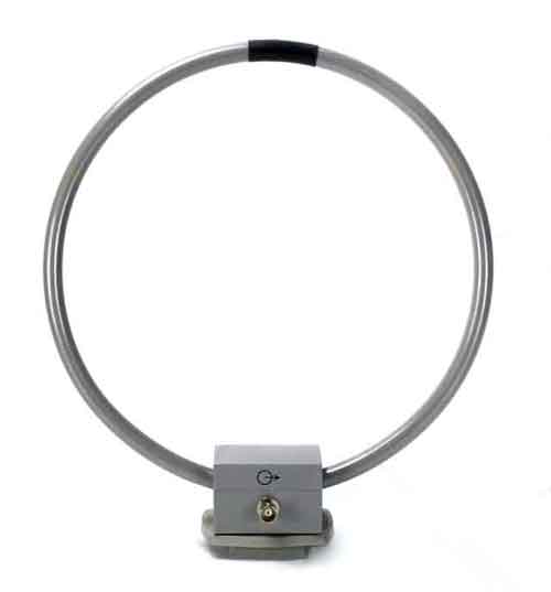
Frequency Range: DC - 3 MHz |
Circular Transmitting Loop Antenna diam. 250 mm DC-3 MHz |
HFRA 5153 Frequency Range: DC - 20 (30) MHz |
Circular Transmitting Loop Antenna diam. 180 mm 0-20 (30) MHz 5 W |
HFRA 5154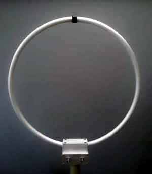 Frequency Range: 100 KHz - 30 MHz |
Circular Transmitting Loop Antenna diam. 100 mm 0.1 - 30 MHz Transformer 50 Ohm 0.5 W |
HFRA 5155 Frequency Range: 100 KHz - 100 (300) MHz |
The HFRA 5155 Loop Antenna for magnetic fields was designed to
create small to medium magnetic fields in the frequency range from 100 kHz to 300 MHz. The HFRA 5155 consists of a shielded single turn loop of 50 mm diameter. The flat frequency response is achieved using a wideband transformer. |
|
HFRA 5156  Frequency Range: DC - 5 MHz |
Circular Transmitting Loop Antenna diam. 50 mm 0-5 MHz 2 W 10 turns |
HFRA 5157 Frequency Range: DC - 20 (30) MHz |
Circular Transmitting Loop Antenna diam. 100 mm 0-20(30) MHz 5 W 2 turns |
|
HFRA 5158
No Image Frequency Range: DC - 2 MHz |
Circular Transmitting Loop Antenna diam. 180 mm 0-2 MHz 5 W 10 turns |
HFRA 5159 Frequency Range: DC - 400 KHz |
Circular Transmitting Loop Antenna diam. 250 mm 0-400 kHz 5 W |
HFRA 5164 Frequency Range: 10 KHz - 120 MHz |
Passive magnetic loop antenna diam. 100 mm 0.01 - 120 MHz 3 turn |
|
HFRA 5170 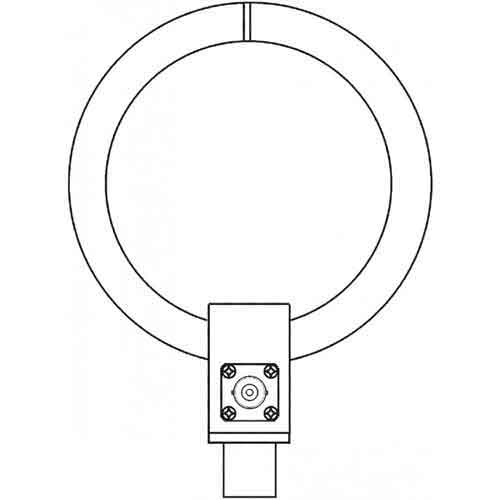 Frequency Range: DC - 30 MHz |
Cal. Loop 3 W diam. 100 mm 0-30 MHz 1 turn 250 Ohm |
|
Copyright © 2001- R. A. Mayes Company, Inc. An Electro Mechanical Research and Development (EMRAD) Corporation, Company See our Privacy Policy All the data files on our website require Adobe Acrobat Reader! |


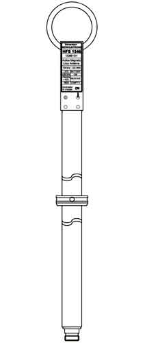


![[Shorter version]](https://www.schwarzbeck.de/Bilder/hfs1546kurz.jpg)