ECAT Lightning Transient Generator Test
System
|
|
ECAT
Lightning Test System
When failure is not an option
RTCA
DO-160, EUROCAE,
SAE,
Boeing, Airbus
and
other avionics test standards
RTCA DO-160E, Section 22
Meets Levels 1 through 5
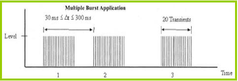
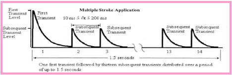
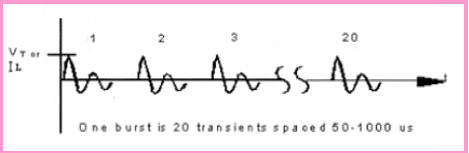
& MultiBurst

|
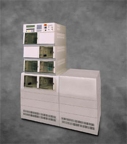
The ECAT Lightning Test System is designed to provide a modular test
platform based on the lightning simulator requirements of RTCA DO-160
Section 22.
The system is expandable to meet Boeing, Airbus and other requirements,
and because of its modular configuration can be easily upgraded as
requirements change.
The basic system configuration provides test capabilities to Level 3 for
Pin Injection, Cable Bundle single and multiple stroke testing, and is
expandable to Level 5 for all waveforms including Waveforms 3H and 6H
for multi burst testing.
|
When failure is not an option. With its fully-automated test
operations, the Thermo Scientific ECAT Lightning Test System (LTS)
yields reliable, repeatable and accurate test results to avionics
lightning simulator requirements of RTCA DO 160E Section 22 E/F. It is
easily expandable to meet Boeing, Airbus, EUROCAE and other
requirements.
Building on the legacy of proven ECAT field-upgradeable modular
technology, it features fast test set-up, intuitive programming,
built-in voltage and current monitoring, and front panel and remote
computer control. On-site calibration and field service is available
worldwide.
|
|
Basic
Components and Modules
|
Model |
Description |
Comments |
|
D104 |
System Control Center |
Includes Virtual Front Panel control with
8x40 character display, Voltage and Current monitor ports
plus communications interface port for computer control and
monitoring |
|
D561 |
Lightning Surge Module for Waveforms 1 and 4 |
6.4us x 69us current (W1) and voltage (W4)
cable bundle single stroke and cable bundle multiple stroke,
plus waveform 4 pin injection tests, all available to Level
5. |
|
D562 |
Lightning Surge Module for Waveform 2 |
100ns x 6.4us Voltage wave for cable bundle
single stroke, cable bundle multiple stroke and multi burst
tests to Level 5. |
|
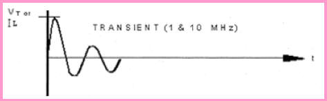
D563 |
Lightning Surge Module for Waveform 3 |
1MHz and 10MHz oscillatory waveforms for pin
injection testing (1MHz) and cable bundle single and
multiple stroke testing to Level 5. An option to this module
is available for Waveform 3H to level 5 for multi burst
testing. |
|
D564 |
Lightning Surge Module for Waveform 5A |
40us x 120us Current wave for pin injection
and single stroke cable bundle testing, available to 2000A
peak currents to meet Boeing requirements which exceed
DO-160 sec. 22 Level 5 requirements |
|
D565 |
Lightning Surge Module for Waveform 5A
and 5B |
All D564
capabilities, plus 50us x 500us current wave for pin
injection and both single and multiple stroke
cable bundle testing. |
|
D566 |
Lightning Surge Module for Waveform 6H |
0.244us x 4us current waveform for cable
bundle multi burst testing |
|
|
Accessories
|
Model |
Description |
Comments |
|
DCI1 |
Cable Induction Coupler |
Provides coupling to cables for cable
injection testing using Waveforms 1, 5A, and 5B |
|
DCV1 |
Ground Injection Coupler |
Coupler for ground injection testing using
Waveforms 4, 5A and 5B. |
|
DPI1 |
Pin Injection Coupler |
Coupler for pin injection testing using
Waveforms 3, 5A and 5B. |
|
DCHF1 |
Cable Induction Coupler |
Provide Cable Induction test capability for
Waveforms 2 and 3 |
|
PK1001D |
Voltage Probe |
Differential high-voltage probes specifically
designed for monitoring surge voltages with rise-times to
10ns and durations to 1000us. Rated to 6kV surge and 277V
rms or dc steady state voltages. |
|
D110 |
Current Probe to 5000A |
0.1V/A +1/-0%; max rms current 65A with
usable rise time from 20ns. |
|
D301X |
Current Probe to 50kA |
0.01V/A +1-0%; max rms current 400A with
usable rise time from 200ns |
|
DJ1 |
Calibration jumpers |
Used for calibration purposes. |
|