|
|
|
|
|
|
|

|
|
|
|
|
|
|
|
|
| EMC Test Systems & LaplaCells |
|
|
Laplace RF Signal Synthesizer | |
|---|---|
|
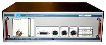
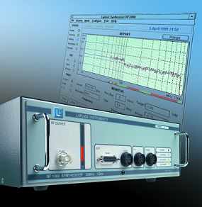
RF6000 RF Signal Synthesizer
80 MHz to 6.0 GHz
Immunity
|
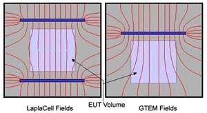
The Laplace range of synthesisers are designed to take the hassle out of
testing to IEC61000-4-3. All aspects of the testing process are controlled by an intelligent Windows software program, included with the hardware. |
|
IEC61000-4-3 immunity testing requires that the EUT
(equipment under test) operates satisfactorily when subject to a strong
electromagnetic field. This requires a scan at a certain fixed level (specified by the standard) of field strength. The scan will comprise a series of steps in frequency. Each step is speci-fied as a percentage of current frequency value. This percentage is variable from 0.5% to 5%. At each step, the frequency is held, the level adjusted to achieve the required field strength as measured by the field sensor, a prescribed modulation mode is initiated and then the conditions held for a dwell time. The EUT should be monitored to de-tect faulty operation during the test. RF Synthesiser.. Does the work for you. The RF6000 and RF3000 immunity test synthesisers and controllers include a signal generator matched to the RFI immunity requirements of IEC61000-4-3. Features such as sine and pulsed modulation, programmable start and stop frequencies, frequency step, and dwell time are provid-ed as standard. The RF3000 covers the range 30MHz to 3GHz. The RF6000 covers the range 30MHz to 6GHz. Both include powerful Windows RFSynth3 control software with USB port interface. When used with the LaplaCell range of test cells, these synthesisers provide full automatic con-trol of field level and all that is needed to provide an automated radiated RF immunity test facili-ty. Advanced features such as pre-scanning, display of EUT status against applied field level and full Windows compatibility are standard. These synthesisers also have all the facilities required for test chamber applications, with an op-tional serial port specifically provided for remote RF sensor connection. Fully compatible with industry standard isotropic RF field probes and sensors, including Holaday, Narda and Radisense. |
|
|
|
|
|
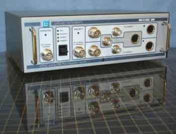
RF3000 RF Signal Synthesizer
80 MHz to 3.0 GHz
Immunity |
PC controlled RF synthesizer for immunity testing matched to the requirements of IEC61000-4-3 and featuring automatic scanning to pre-programmed schedules. To make the best use of the immunity test facilities for both compliance testing and product investigations, several useful features have been developed. |
|
These include:
The system is controlled from any PC via a Windows software package and serial port. No additional interface cards are required. |
|
|
|
|
|
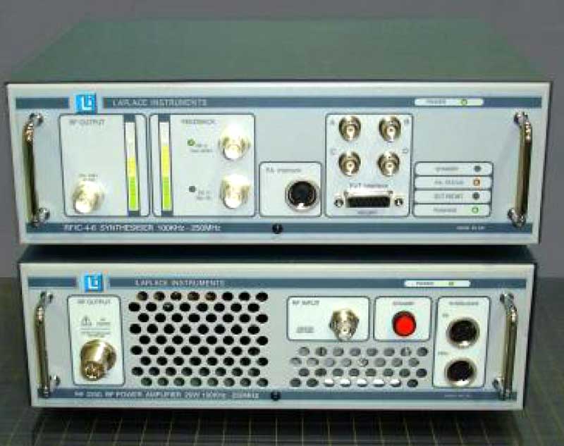
RFIC-4-6 RF Signal Synthesizer DC to 100 Hz
Conducted Immunity
|
The Laplace model RFIC conducted immunity system
• RFIC-4-6 synthesiser and interface unit. This |
|
This system will
test EUTs to more than the 10V stress level required by industrial
standards. The x46xx range of CDNs cover all standard cable types
with the unique benefit of versatility, each type being configurable
to suit several different cables. In addition, the system will operate with "Enhanced" CDNs which offer closed loop control for better stress level accuracy, more efficient use of RF |
|
Laplace RF Power Amplifiers | |||||||||||||||||||||||||||||
|---|---|---|---|---|---|---|---|---|---|---|---|---|---|---|---|---|---|---|---|---|---|---|---|---|---|---|---|---|---|
|
Power Amplifiers 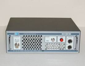
|
The RF power amplifier range from Laplace is specifically designed for EMC Immunity testing. These are compact units with characteristics matched to the requirements of IEC standards. | ||||||||||||||||||||||||||||
| These RF amplifiers utilize fully isolated linear MOSFET or advanced GaAs FET devices, which provide high gain, wide dynamic range and excellent third order intercepts. High efficiency and reliable operation are achieved by employing unique RF combining circuits, RF microstrip networks, sophisticated thermal design, custom machined housing and heavy duty components. The high power RF amplifiers undergo extensive burn-in prior to final test and inspection. The amplifiers all feature 50ohm input & output impedance, thermal and mismatch protection, standby switch and internal fan assisted cooling. | |||||||||||||||||||||||||||||
|
|||||||||||||||||||||||||||||
|
|
|||||||||||||||||||||||||||||
|
LETIS
 |
Frequency range 30MHz - 6GHz RF Input/output impedance 50 ohm RF Input/output connectors N type RF power rating 60W RF Signal connectors BNC Interlock signals 4 way DIN (metal/screened) Connectivity: Cell/antenna to: PA1, PA2, Receiver/analyzer Synthesizer RF to: PA1, PA2 Synthesizer interlock to: PA1, PA2 Insertion loss (RF) 1dB max Control Auto: USB Man mode: Paddle switch Indication LED indicators . Power 110/230V 50/60Hz IEC input Size (W x H x D) 31 x 11 x 26 Weight 3.5kg | ||||||||||||||||||||||||||||
|
| |||||||||||||||||||||||||||||
|
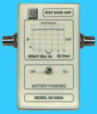
SA1020 RF Pre-Amplifier
18dB Gain
5KHz to 500MHz
|
| ||||||||||||||||||||||||||||
Laplace EMC Spectrum Analyzers | |
|---|---|
|
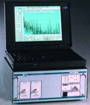
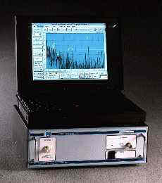
SA3000
Spectrum Analyzer 10 kHz to 3.0 GHz EMC Analyzer
Emissions and CISPR standards |
The Laplace SA3000 EMC analyzer provides an exceptionally cost effective tool to manufacturers and others who wish to measure EMC emissions from their products. Entirely controlled from an intuitive Windows software package, the analyzer can enable a self-test and self-certification strategy to be adopted with confidence.
|
|
|
|
|
SA1002
10 kHz to 1.0 GHz EMC Spectrum Analyzer Emissions
& CISPR Standards
|
The SA1002 is an exceptionally well featured EMC analyzer designed to match
the requirements of all common EMC standards and includes..
|
|
Software is at the heart of any EMC test system. The Laplace RF emissions
software is a fully integrated Windows compliant package. It not only
directly controls all aspects of the analyzer, it sets the test conditions such as input device, antenna correction and insertion loss. It also includes unique features which can cancel ambient signals, calibrate your radiated test site (in conjunction with an ERS) and provide instant zoom anywhere in the scan. This software is specifically designed for ease of use by non- EMC expert staff, but retains many exceptionally advanced features. Finally...The Laplace range is fully supported worldwide. Help lines and lifetime software support are included for all our customers. |
|
Laplace Large Loop Antenna | |
|
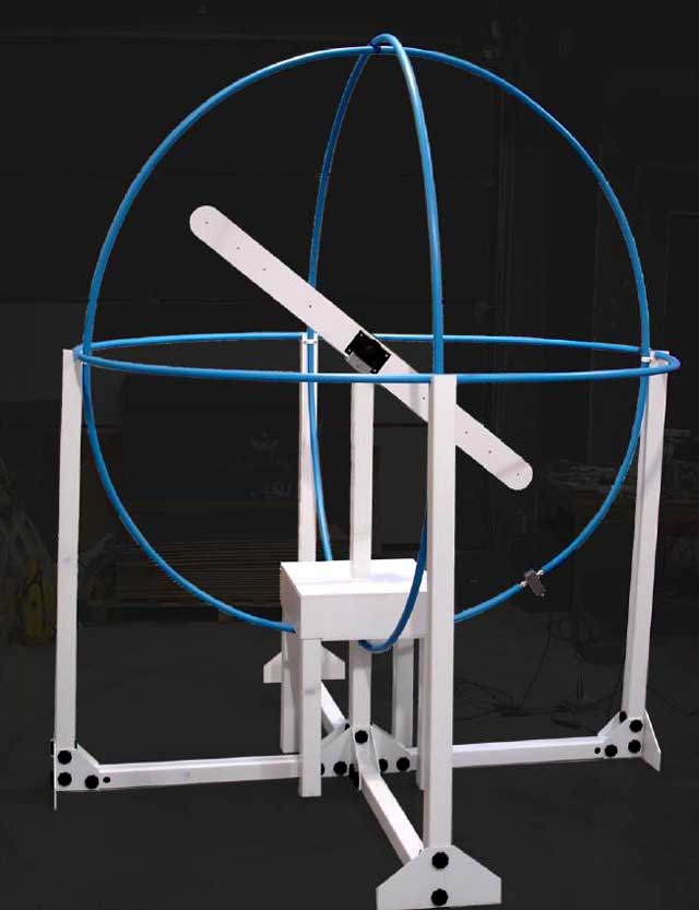
Large Loop Antenna
Fully Calibrated
9KHz - 30MHz
Fully compliant with CISPR15 Luminaire Test (EN55015) | The RF300 is a fully compliant and calibrated 2 metre diameter triple Van Veen Loop. This antenna is specifically manufactured in accordance with CISPR16 for the compliance testing of luminaires as required by EN 55015. |
|
The RF300 is complete with 3 axes loops and all cables and loop selector
patch panel. The supporting structure features a rigid non-metallic PVC frame designed for ease of assembly yet reducing to a compact size for transportation and storage. The current sensors fitted to each loop feature a fully screened passive inductor design that avoids any issues related to overload or compression. An optional calibration loop (RF300C) is available. This includes a stand and pivot adaptors to enable use with vertical and horizontal loops. Use of the calibration loop ensures that on-site calibration can be achieved, thus eliminating any effects due to the surroundings. Note that a suitable signal source with 1v rms, 50 ohm output is required (not included with the RF300C). | |
|
Copyright © 2001-2023 R. A. Mayes Company, Inc. An Electro Mechanical Research and Development (EMRAD) Corporation, Company See our Privacy Policy All the data files on our website require Adobe Acrobat Reader! |